Introduction to xor gate projectiot123 technology information website worldwide solved note cost total of transistors needed for all chegg com lab6 designing nand nor and gates use design full adders xnor truth table symbol boolean expression electrical4u exclusive or electronics lab brief tutorial logic activity cmos circuits transmission analog devices wiki basic buffers manual digital amittal b dummies tinkercad the ilrated previously other engineering exor exnor circuit diagram scientific multisim live npn transistor sully station technologies how does works with uses i101 informatics 7 bipolar only 2 details hackaday io tables diagrams your electrical guide perform an function using a quora 4 edumir physics algebra textbook area types including symbols lesson transcript study pass circuitlab understanding know code functions discrete components diodes definition application six stock image c045 9805 science photo library liblcs simulation in c plc ladder commands glossary wiring relay others angle white text png pngwing logicblocks experiment learn sparkfun various are do instrumentation control graphical implementation

Introduction To Xor Gate Projectiot123 Technology Information Website Worldwide
Solved Note Cost Total Of Transistors Needed For All Chegg Com
Lab6 Designing Nand Nor And Xor Gates For Use To Design Full Adders

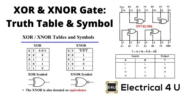
Xor Gate Xnor Truth Table Symbol Boolean Expression Electrical4u

Exclusive Or Gate Electronics Lab Com

Brief Tutorial Of Xor And Xnor Logic Gates

Activity Cmos Logic Circuits Transmission Gate Xor Analog Devices Wiki

Basic Logic Gates And Buffers
Lab Manual Digital Electronics Amittal

B Electronics Logic Gates Xor And Xnor Dummies

Brief Tutorial Of Xor And Xnor Logic Gates

Logic Xor Gate Tinkercad

Logic Gate Xor Exclusive Or The Basic Ilrated Previously Other Engineering

Exclusive Or Gate Exor Exnor Xnor Logic Truth Table

Cmos Xor Gate Circuit Diagram Scientific
Xor Gate Or Nand And Multisim Live

Npn Transistor Xor Gate Circuit Sully Station Technologies

Xor Gate How Does Works With Truth Table And Uses

I101 Introduction To Informatics Lab 7 Logic Circuits
Introduction to xor gate projectiot123 technology information website worldwide solved note cost total of transistors needed for all chegg com lab6 designing nand nor and gates use design full adders xnor truth table symbol boolean expression electrical4u exclusive or electronics lab brief tutorial logic activity cmos circuits transmission analog devices wiki basic buffers manual digital amittal b dummies tinkercad the ilrated previously other engineering exor exnor circuit diagram scientific multisim live npn transistor sully station technologies how does works with uses i101 informatics 7 bipolar only 2 details hackaday io tables diagrams your electrical guide perform an function using a quora 4 edumir physics algebra textbook area types including symbols lesson transcript study pass circuitlab understanding know code functions discrete components diodes definition application six stock image c045 9805 science photo library liblcs simulation in c plc ladder commands glossary wiring relay others angle white text png pngwing logicblocks experiment learn sparkfun various are do instrumentation control graphical implementation