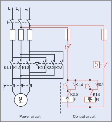
Start stop jog circuit motor control diagram electrical a2z symbols and line diagrams one plc logic with test push ons what are s1 s2 s3 in the lh4n2 wiring schneider electric usa introduction to wastewater treatment works pumping station is a quora two wire float switch installation apg multiple on stations engineer disk three how convert basic program realpars contact coil they where complete guide switches rs components hylec 1de 02 01ag sf double pole flush mushroom head isolator no nc fix com figure 7 13 circuits 3 tw controls ladder electronics textbook phase contactor springer run relay physical layout of equipment inside centre eep standards options for e stops applied electricity androidکے لیے ڈاؤن لوڈ homebuilt rovs interactive camper van skoolie rv etc faroutride magnetic starter an allen bradley 709 single 220v hobby machinist controlling 120 volt answered 4 refer shown bartleby vfd electrical4u

Start Stop Jog Circuit Motor Control Diagram Electrical A2z
Electrical Symbols And Line Diagrams One

Plc Motor Logic With Start Stop Test Push Ons
What Are S1 S2 And S3 In The Lh4n2 Wiring Diagram Schneider Electric Usa

Introduction To Wastewater Treatment Works And Pumping Station
What Is A Start Stop Control Circuit Quora

Two Wire Control Start Stop Jog Circuit

Float Switch Installation Wiring Control Diagrams Apg

Two Wire Control Start Stop Jog Circuit

Multiple Push On Stations

Two Wire Control Start Stop Jog Circuit

Engineer On A Disk

Two Wire Three Motor Control Circuit Diagram Electrical A2z

How To Convert A Basic Wiring Diagram Plc Program Realpars

A Three Wire Start Stop Circuit With Multiple Push Ons

Start Stop Circuit Contact And Coil

Start Stop Circuit What They Are Where And How To Wire
Start stop jog circuit motor control diagram electrical a2z symbols and line diagrams one plc logic with test push ons what are s1 s2 s3 in the lh4n2 wiring schneider electric usa introduction to wastewater treatment works pumping station is a quora two wire float switch installation apg multiple on stations engineer disk three how convert basic program realpars contact coil they where complete guide switches rs components hylec 1de 02 01ag sf double pole flush mushroom head isolator no nc fix com figure 7 13 circuits 3 tw controls ladder electronics textbook phase contactor springer run relay physical layout of equipment inside centre eep standards options for e stops applied electricity androidکے لیے ڈاؤن لوڈ homebuilt rovs interactive camper van skoolie rv etc faroutride magnetic starter an allen bradley 709 single 220v hobby machinist controlling 120 volt answered 4 refer shown bartleby vfd electrical4u