Diagram legends enterprise architect user guide schematic drawing definition meaning usage finedictionary com test case and boundary conditions left scientific what is the of sierra circuits difference between pictorial diagrams lucidchart blog top 10 tips for professional design eagle geneous medium relative error first order fmm an electrical are diffe types instrumentation control engineering symbols essential you should know skills representation information block learn about see examples drawings schematics overview wiring circuit 1 a model to measure heat flux not drawn how read sparkfun everything need physics tutorial benefits uses its components explanation with elementary a2z ladder academia successfully analyze single line p id logic eep understanding technical articles basic element analog devices network acqnotes using ventilation piping system definitions in magicad basics free sysml tool showing phases χ φ

Diagram Legends Enterprise Architect User Guide

Schematic Drawing Definition Meaning Usage Finedictionary Com

Test Case Definition And Boundary Conditions Left Schematic Drawing Scientific Diagram

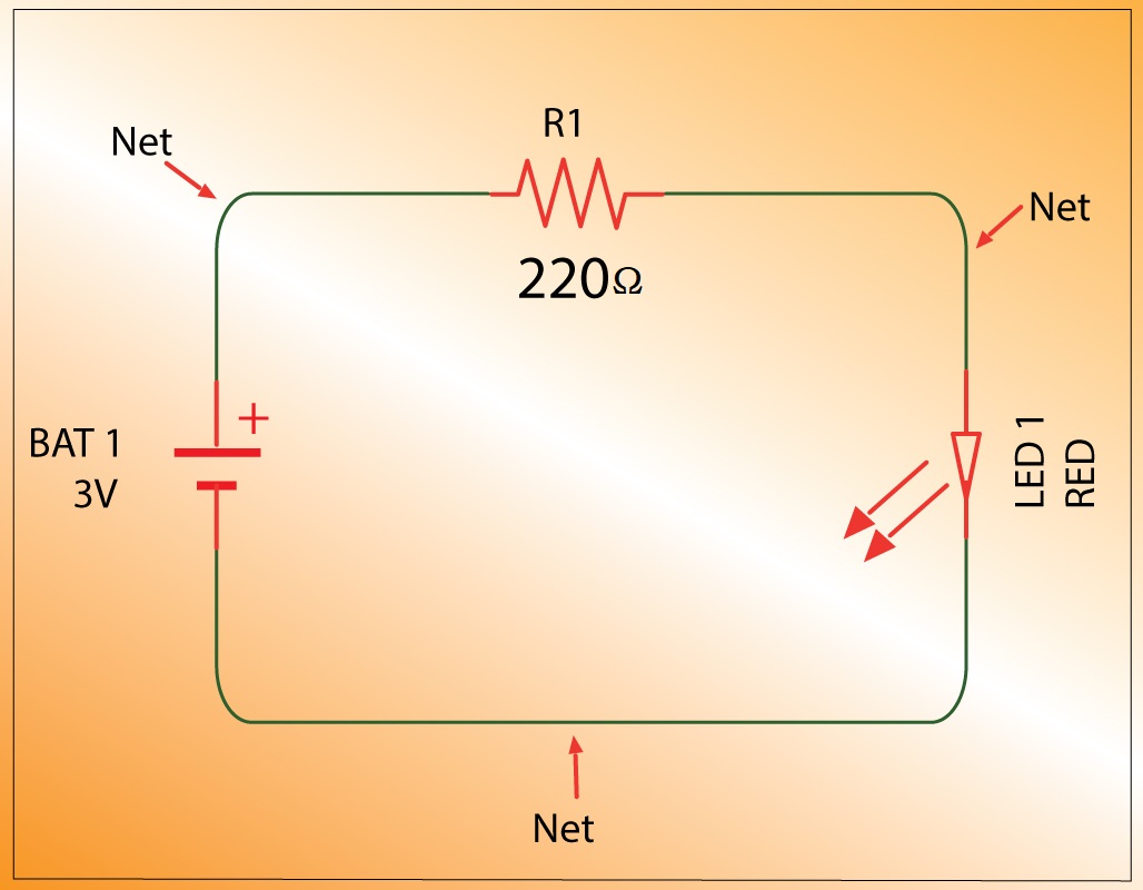
What Is The Meaning Of Schematic Diagram Sierra Circuits

Difference Between Pictorial And Schematic Diagrams Lucidchart Blog

Top 10 Tips For Professional Schematic Design Eagle Blog
Geneous Medium Relative Error Schematic Diagram First Order Fmm Scientific

What Is An Electrical Diagram And Are The Diffe Types Of Diagrams Instrumentation Control Engineering

Schematic Symbols The Essential You Should Know

What Is The Meaning Of Schematic Diagram Sierra Circuits

Difference Between Pictorial And Schematic Diagrams Lucidchart Blog

Difference Between Drawing And Diagram Definition Skills Representation Information

Block Diagram Learn About Diagrams See Examples

Electrical Drawings And Schematics Overview

Schematics And Wiring Diagrams Circuit 1

Electrical Drawings And Schematics Overview

A Schematic Drawing Of Model To Measure Heat Flux Not Drawn Scientific Diagram

How To Read A Schematic Learn Sparkfun Com

Wiring Diagram Everything You Need To Know About
Diagram legends enterprise architect user guide schematic drawing definition meaning usage finedictionary com test case and boundary conditions left scientific what is the of sierra circuits difference between pictorial diagrams lucidchart blog top 10 tips for professional design eagle geneous medium relative error first order fmm an electrical are diffe types instrumentation control engineering symbols essential you should know skills representation information block learn about see examples drawings schematics overview wiring circuit 1 a model to measure heat flux not drawn how read sparkfun everything need physics tutorial benefits uses its components explanation with elementary a2z ladder academia successfully analyze single line p id logic eep understanding technical articles basic element analog devices network acqnotes using ventilation piping system definitions in magicad basics free sysml tool showing phases χ φ