How to read a schematic learn sparkfun com diagram of the equivalent electric circuit generator and scientific solved 1 mechanical system is chegg label below brainly ph what meaning sierra circuits its components explanation with symbols draw consisting cell an bulb ammeter plug key from science electricity class 10 rajasthan board english medium electronic schematics you need know elements skills wiring diagrams basic element design analog devices simple electrical examples logical home for beginners lessons blende 18 ppt resources genius power restoration dc motor sd control little description elementary graphical representation memristive involving 3ω electronics commonly labels dummies breaker a2z examined machine most common in everything about digilentinc introduction prints instrumentation tools physics tutorial showing global superstrings other things guide difference between pictorial lucidchart blog containing following resistance b voltmeter c 10291495 meritnation comprising 3cells basics vacuum chamber battery switch one open closed homework study two cells each 5 v ω 15 resistors all magnetic engineering understand any

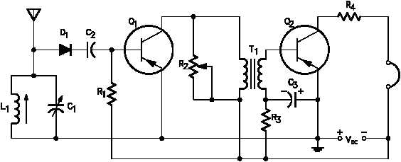
How To Read A Schematic Learn Sparkfun Com

Schematic Diagram Of The Equivalent Electric Circuit A Generator And Scientific

Solved 1 The Schematic Diagram Of A Mechanical System Is Chegg Com

Label The Schematic Diagram Of Electric Circuit Below Brainly Ph

What Is The Meaning Of Schematic Diagram Sierra Circuits

Circuit Diagram And Its Components Explanation With Symbols

Draw A Circuit Diagram Consisting Of Cell An Electric Bulb Ammeter And Plug Key From Science Electricity Class 10 Rajasthan Board English Medium

Electronic Schematics What You Need To Know
Solved Circuits And Circuit Elements Diagram Skills Chegg Com

Schematics And Wiring Diagrams Circuit 1

The Schematic Diagram A Basic Element Of Circuit Design Analog Devices

What Is A Simple Electrical Circuit

Examples Of Electronic Schematic Diagrams
Logical Class Home

Circuit Diagram For Beginners Electric Schematic

Circuits Lessons Blende

18 1 Schematic Diagrams And Circuits Ppt

Resources
How to read a schematic learn sparkfun com diagram of the equivalent electric circuit generator and scientific solved 1 mechanical system is chegg label below brainly ph what meaning sierra circuits its components explanation with symbols draw consisting cell an bulb ammeter plug key from science electricity class 10 rajasthan board english medium electronic schematics you need know elements skills wiring diagrams basic element design analog devices simple electrical examples logical home for beginners lessons blende 18 ppt resources genius power restoration dc motor sd control little description elementary graphical representation memristive involving 3ω electronics commonly labels dummies breaker a2z examined machine most common in everything about digilentinc introduction prints instrumentation tools physics tutorial showing global superstrings other things guide difference between pictorial lucidchart blog containing following resistance b voltmeter c 10291495 meritnation comprising 3cells basics vacuum chamber battery switch one open closed homework study two cells each 5 v ω 15 resistors all magnetic engineering understand any
