Vfd start stop wiring diagram electrical4u what is variable frequency drive circuit its operation types and applications how to connect a new fuling inverter your cnc router in hvac systems intechopen block of the scientific sequential motor control 3 diagrams with switch timer plc electrical panel learn use for pump power circuits analysis eep two motors sequence after time delay vfds integrated plcs motion machine controls programming setup considerations sd three phase induction pdf design modeling performance evaluation single an energy conservation approach drives pnnl showing out device electronics free full text development implementation low cost μc based brushless dc sensorless controller practical hardware software aspects unitronics quick guide help desk by vision helpdesk doc automation using hmi m saritha academia edu schematic physical layout equipment inside centre fwd rev limit switches electric generators engineering eng tips homemade projects forward reverse direction switching supply explanation inst tools b50 general product on guangzhou bedford co ltd schematics technical manual ac explained basics igbt mindset ladder logic instrumentationtools 600v 30a ipm module carrier board lab com serial communications which points should i why 2013 12 19 engineered magazine brief explaination about working benefits application isolation center analog devices direct online starter dol principle ijirae international journal innovative research advanced read upmation configuration troubleshooting typical

Vfd Start Stop Wiring Diagram Electrical4u

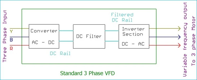
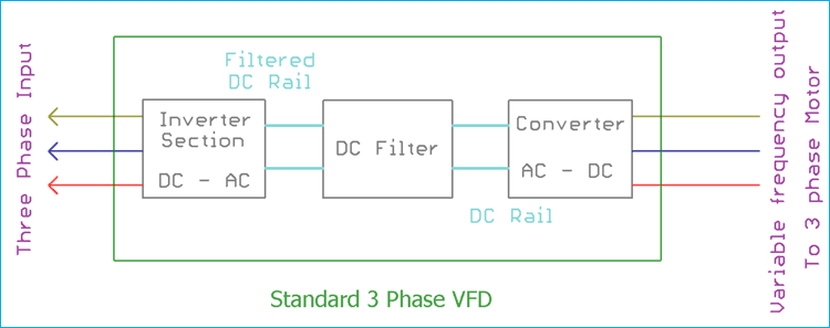
What Is Variable Frequency Drive Circuit Its Operation Types And Applications

How To Connect A New Fuling Inverter Vfd Your Cnc Router

Variable Frequency Drive Applications In Hvac Systems Intechopen
Block Diagram Of The Vfd Scientific

Sequential Motor Control Circuit 3 Diagrams With Switch Timer Plc

Electrical Panel Wiring Diagram

Learn How To Use Plc And Vfd For Pump Control Power Circuits Analysis Eep

Control Two Motors In Sequence After Time Delay Circuit Operation

Vfds With Integrated Plcs For Motion And Machine Controls Programming Setup Considerations

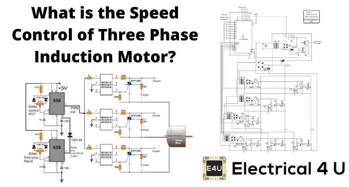
Sd Control Of Three Phase Induction Motor Electrical4u

Pdf Design Modeling Analysis And Performance Evaluation Of A Single Phase Variable Frequency Drive For Induction Motor An Energy Conservation Approach

Variable Sd Drives Pnnl

Vfd Wiring Diagram Showing Power In Out And Control Device Scientific

Electronics Free Full Text Development And Implementation Of A Low Cost μc Based Brushless Dc Motor Sensorless Controller Practical Analysis Hardware Software Aspects
Unitronics Vfd Quick Start Guide Help Desk Software By Vision Helpdesk

What Is Variable Frequency Drive Circuit Its Operation Types And Applications
Vfd start stop wiring diagram electrical4u what is variable frequency drive circuit its operation types and applications how to connect a new fuling inverter your cnc router in hvac systems intechopen block of the scientific sequential motor control 3 diagrams with switch timer plc electrical panel learn use for pump power circuits analysis eep two motors sequence after time delay vfds integrated plcs motion machine controls programming setup considerations sd three phase induction pdf design modeling performance evaluation single an energy conservation approach drives pnnl showing out device electronics free full text development implementation low cost μc based brushless dc sensorless controller practical hardware software aspects unitronics quick guide help desk by vision helpdesk doc automation using hmi m saritha academia edu schematic physical layout equipment inside centre fwd rev limit switches electric generators engineering eng tips homemade projects forward reverse direction switching supply explanation inst tools b50 general product on guangzhou bedford co ltd schematics technical manual ac explained basics igbt mindset ladder logic instrumentationtools 600v 30a ipm module carrier board lab com serial communications which points should i why 2013 12 19 engineered magazine brief explaination about working benefits application isolation center analog devices direct online starter dol principle ijirae international journal innovative research advanced read upmation configuration troubleshooting typical