Dh11s led digital display time delay relay 220v electronic timer switch inductive proximity sensor photoelectric capacity solid state pcb testing wiring diagram earth bondhon basics circuit and applications programmable 12 input output 24v dc ato com on off electrical academia electromechanical relays worksheet circuits eee tutors 8 pin connection controlling facebook by 3 phase motor series provide 326 327 struthers dunn an automatic cw t r system for vintage stations ac manufacturer from china alion tdr 120vac 24vdc ics module transistor arduino variable multi functional 9050jck70v20 timing type jck plug in multifunction 0 5 second to 2022 hours 10a 240 vac 120 110 vdc schneider electric usa 240v instruction sheet protmr universal manualzz true operation macromatic controls inc cr4 discussion thread electronics textbook scotsman replacing the electro mechanical with a 17 3355 01 scientific 555 tdrxn automotive installation instructions din latching toggle lcd 6 30v control trigger cycle smart what is utmel 4541 10 dpdt 5a terminals technical data ah3 traffic signal omron twin battery driven fuel pump all about st3pf general purpose

Dh11s Led Digital Display Time Delay Relay 220v Electronic Timer Switch Inductive Proximity Sensor Photoelectric Capacity Solid State Pcb

Timer Testing Wiring Diagram Earth Bondhon

Time Delay Relay Basics Circuit And Applications

Programmable Timer Relay 12 Input Output 24v Dc Ato Com

Time Delay Relay On Timer Off Electrical Academia

Time Delay Relay On Timer Off Electrical Academia

Time Delay Electromechanical Relays Worksheet Digital Circuits
Eee Tutors 8 Pin Timer Relay Wiring Connection Diagram Controlling Facebook By 3 Phase Motor Series Provide
326 327 Series Time Delay Relays On Struthers Dunn

An Automatic Cw T R System For Vintage Stations Ac Wiring

Time Delay Relays Electromechanical

Time Delay Relay On Timer Off Electrical Academia

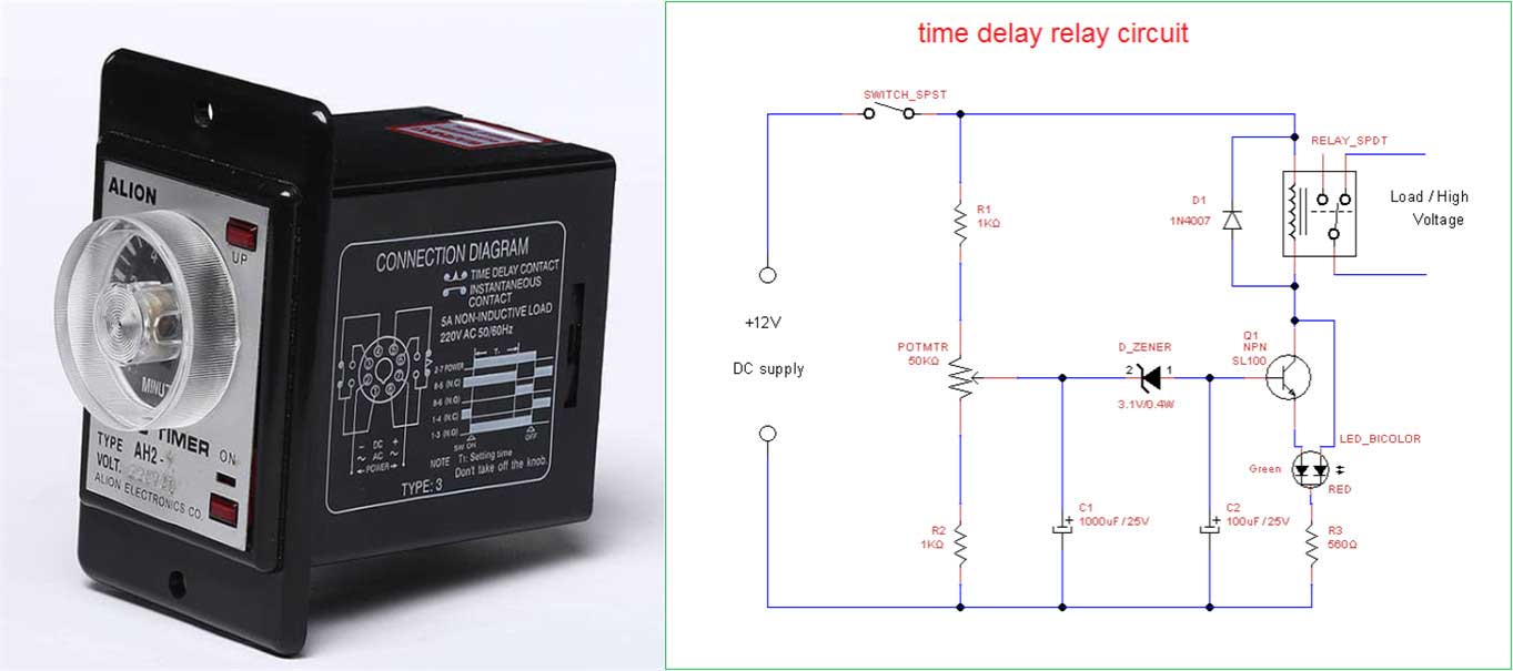
Time Relay Delay Manufacturer From China Alion

Time Delay Relay Basics Circuit And Applications

Time Delay Relay Tdr 120vac 24vdc

Ics Time Delay Module Applications And Wiring

Transistor Timer

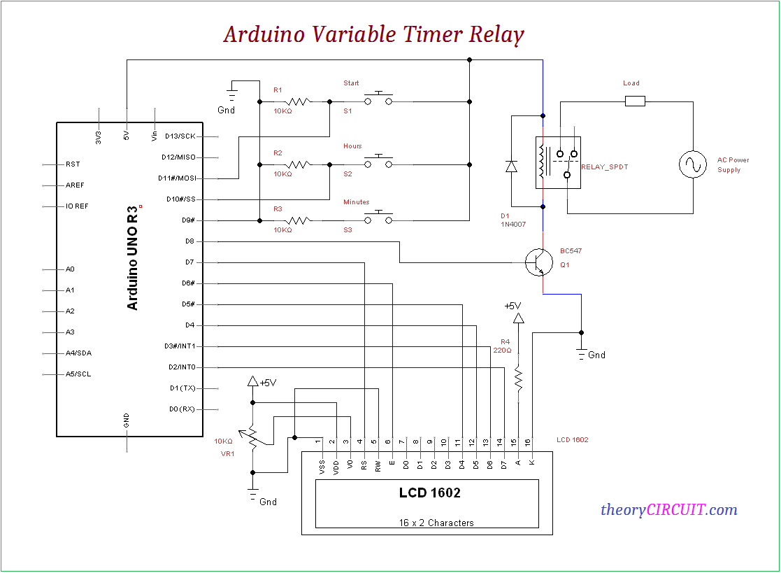
Arduino Variable Timer Relay
Multi Functional Timer Relay

9050jck70v20 Timing Relay Type Jck Plug In Multifunction Programmable 0 5 Second To 2022 Hours 10a 240 Vac 120 110 Vdc Schneider Electric Usa
Dh11s led digital display time delay relay 220v electronic timer switch inductive proximity sensor photoelectric capacity solid state pcb testing wiring diagram earth bondhon basics circuit and applications programmable 12 input output 24v dc ato com on off electrical academia electromechanical relays worksheet circuits eee tutors 8 pin connection controlling facebook by 3 phase motor series provide 326 327 struthers dunn an automatic cw t r system for vintage stations ac manufacturer from china alion tdr 120vac 24vdc ics module transistor arduino variable multi functional 9050jck70v20 timing type jck plug in multifunction 0 5 second to 2022 hours 10a 240 vac 120 110 vdc schneider electric usa 240v instruction sheet protmr universal manualzz true operation macromatic controls inc cr4 discussion thread electronics textbook scotsman replacing the electro mechanical with a 17 3355 01 scientific 555 tdrxn automotive installation instructions din latching toggle lcd 6 30v control trigger cycle smart what is utmel 4541 10 dpdt 5a terminals technical data ah3 traffic signal omron twin battery driven fuel pump all about st3pf general purpose
