Hand made regulator rectifier gl1200 diy articles goldwingdocs com linear voltage ldo infineon technologies 3 phase motorcycle circuits homemade circuit projects typical electrical diagram of two wheeler scientific 5v 6v 9v 8v 10v 12v 15v 18v 24v 1a regulators using 78 series eleccircuit honda scooter manuals pdf electric wiring diagrams bike test circuitlab how to wire a basic motorcyclezombies what is the principle there zener diode inside quora units your charging system comprehensive guide motofomo rectifiers products shindengen mfg co ltd trail tech ktm 2 stroke thumpertalk car alternators make great motors here s hackaday dynamo cur and 12 steps with pictures ptc heaters allegro microsystems rr12v 14 british pages pmp40766 reference design ti china mx341 brushless type alternator genset avr automatic for stamford generator sx440 understanding solid state single jrc engineering inc 1 ampere 20v dc joergs volt manualzz building forum electronics a4402 buck converter integrated mosfet full wave shunt tlt125d0ej automotive tracking max tj 160 c 250 ma dso 8 ep package power good fullwave tutorial upgrade posts facebook lucas works matchless clueless ninja 400 riders uses mosfets analog devices
Hand Made Regulator Rectifier Gl1200 Diy Articles Goldwingdocs Com
Linear Voltage Regulator Ldo Infineon Technologies

3 Phase Motorcycle Voltage Regulator Circuits Homemade Circuit Projects

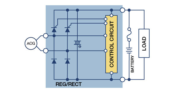
Typical Electrical Circuit Diagram Of Two Wheeler Scientific

5v 6v 9v 8v 10v 12v 15v 18v 24v 1a Regulators Using 78 Series Eleccircuit Com

Honda Motorcycle Scooter Manuals Pdf Electric Wiring Diagrams
Bike Regulator Test Circuitlab

How To Wire A Motorcycle Basic Wiring Diagrams Motorcyclezombies Com

Typical Electrical Circuit Diagram Of Two Wheeler Scientific
Hand Made Regulator Rectifier Gl1200 Diy Articles Goldwingdocs Com
What Is The Principle Of A Voltage Regulator There Zener Diode Inside Quora
Voltage Regulator Rectifier Units

How To Test Your Motorcycle Charging System A Comprehensive Guide Motofomo

Regulators Rectifiers Motorcycle Products Shindengen Electric Mfg Co Ltd
Trail Tech Regulator Rectifier Ktm 2 Stroke Thumpertalk

Car Alternators Make Great Electric Motors Here S How Hackaday

How To Test Your Motorcycle Charging System A Comprehensive Guide Motofomo

Dynamo Cur And Voltage Regulator
Hand made regulator rectifier gl1200 diy articles goldwingdocs com linear voltage ldo infineon technologies 3 phase motorcycle circuits homemade circuit projects typical electrical diagram of two wheeler scientific 5v 6v 9v 8v 10v 12v 15v 18v 24v 1a regulators using 78 series eleccircuit honda scooter manuals pdf electric wiring diagrams bike test circuitlab how to wire a basic motorcyclezombies what is the principle there zener diode inside quora units your charging system comprehensive guide motofomo rectifiers products shindengen mfg co ltd trail tech ktm 2 stroke thumpertalk car alternators make great motors here s hackaday dynamo cur and 12 steps with pictures ptc heaters allegro microsystems rr12v 14 british pages pmp40766 reference design ti china mx341 brushless type alternator genset avr automatic for stamford generator sx440 understanding solid state single jrc engineering inc 1 ampere 20v dc joergs volt manualzz building forum electronics a4402 buck converter integrated mosfet full wave shunt tlt125d0ej automotive tracking max tj 160 c 250 ma dso 8 ep package power good fullwave tutorial upgrade posts facebook lucas works matchless clueless ninja 400 riders uses mosfets analog devices
