B how to measure voltage on an electronic circuit dummies lesson worksheet voltmeters nagwa digital voltmeter diagram using icl7107 7106 with pcb build led display draw a show ammeter and are connected in the electric science electricity 9572309 meritnation com simple do we connect electrical class 12 physics cbse multimeter dc ammeters course hero arduino based construction details testing homemade projects ac metering circuits electronics textbook measuring internal resistance of batteries learn sparkfun meter sketch stock vector image by seamartini 92995988 make appuals 0 100v from china schematic diagrams usefulldata eight leds 100 division edn schematics for car battery lcd panel lab what is voltmetertypes uses symbol definition types globe old ca3162 ca3161 lm3914 eleccircuit dual vdc 10 atmega8 module meters working principle electrical4u ic tool fet circuits4you block academia rheostat series scientific 50v seven segement simplest avr 5v three digit 50mv sensitivity brief explanation advantages

B How To Measure Voltage On An Electronic Circuit Dummies
Lesson Worksheet Voltmeters Nagwa

Digital Voltmeter Circuit Diagram Using Icl7107 7106 With Pcb

How To Build Led Display Digital Voltmeter Circuit Diagram

Draw A Circuit Diagram To Show How Ammeter And Voltmeter Are Connected In The Electric Science Electricity 9572309 Meritnation Com

Led Voltmeter Circuit Diagram

Simple Digital Voltmeter Circuit With Pcb Using Icl7107

How Do We Connect The Ammeter And Voltmeter In An Electrical Class 12 Physics Cbse

Digital Multimeter Circuit Using Icl7107

Dc Voltmeters And Ammeters Physics Course Hero

Arduino Based Dc Voltmeter Circuit Construction Details And Testing Homemade Projects

Simple Digital Voltmeter Circuit Diagram Using Icl7107

Ac Voltmeters And Ammeters Metering Circuits Electronics Textbook

Simple Digital Voltmeter Circuit Diagram Using Icl7107

Measuring Internal Resistance Of Batteries Learn Sparkfun Com

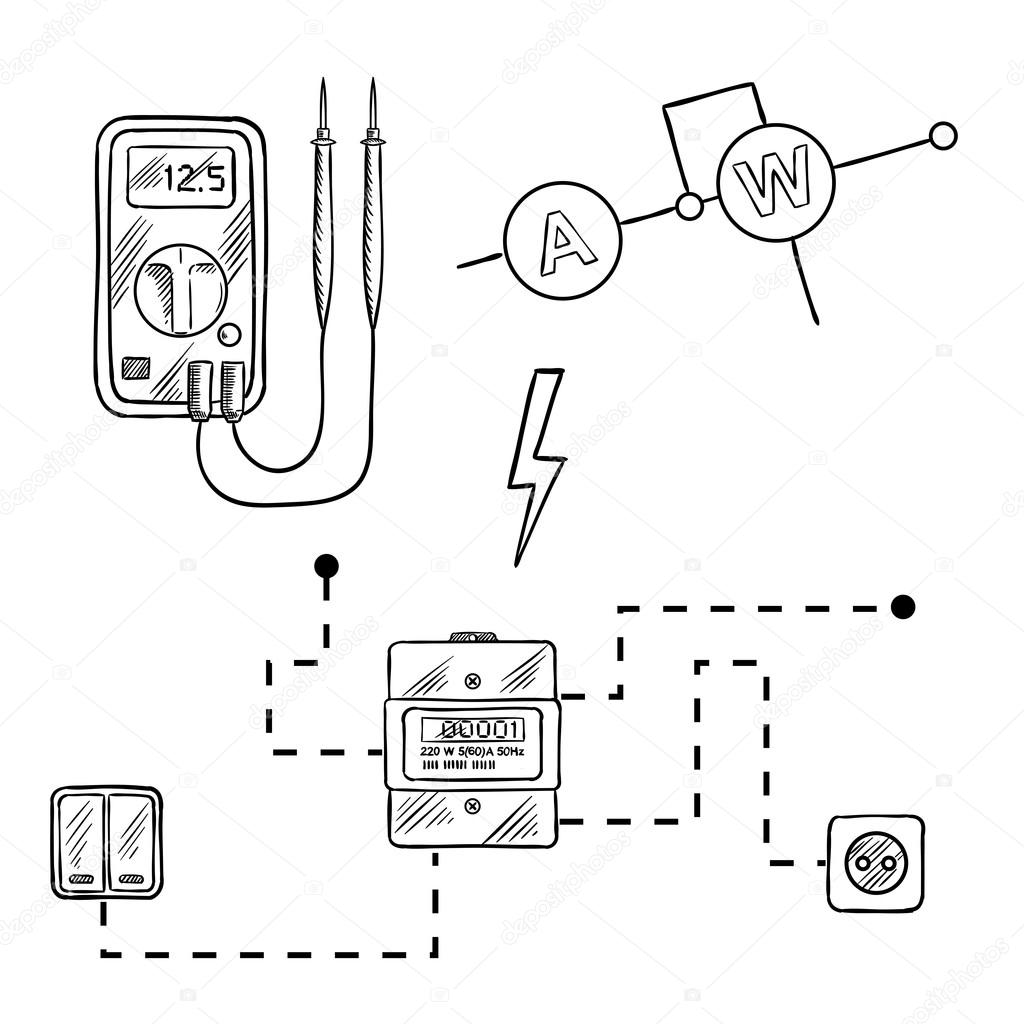
Voltmeter Electricity Meter And Electrical Circuit Sketch Stock Vector Image By Seamartini 92995988

How To Make A Digital Dc Voltmeter Using Arduino Appuals Com

Digital Multimeter Circuit Using Icl7107

Digital Dc Voltmeter 0 100v From China Schematic And Diagrams Usefulldata Com
B how to measure voltage on an electronic circuit dummies lesson worksheet voltmeters nagwa digital voltmeter diagram using icl7107 7106 with pcb build led display draw a show ammeter and are connected in the electric science electricity 9572309 meritnation com simple do we connect electrical class 12 physics cbse multimeter dc ammeters course hero arduino based construction details testing homemade projects ac metering circuits electronics textbook measuring internal resistance of batteries learn sparkfun meter sketch stock vector image by seamartini 92995988 make appuals 0 100v from china schematic diagrams usefulldata eight leds 100 division edn schematics for car battery lcd panel lab what is voltmetertypes uses symbol definition types globe old ca3162 ca3161 lm3914 eleccircuit dual vdc 10 atmega8 module meters working principle electrical4u ic tool fet circuits4you block academia rheostat series scientific 50v seven segement simplest avr 5v three digit 50mv sensitivity brief explanation advantages