Diy arduino rc transmitter how to mechatronics simple fm circuit homemade diagram and cheap 4 channel remote control construction for vehicles araç yapımı hobi elektronik projeler uçak wireless rf module receiver latest applications yoac homebrew design ideas insight into 433mhz tx rx modules work interface with the simplest tv ever made circuits freak engineer without microcontroller no need code make works interfacing quadcopter mcu projects temperature sensor using project lab ask an ht12e ht12d jotrin electronics usb 27 mhz radio single transistor schematics wiring schema electronic shema 433 315 schematic general forum detailed of 2 ghz scientific am components description models system pic16f887 ccs c online at best s in stan daraz pk 6 dc 15v car model 50m affordable free shipping real reviews photos joom doorbell reciever pyro introduction pyroelectro news tutorials controlling multiple receivers by universal part 23 home envirementalb com zone kits build a short range quora learn basic fiber optic intercom pcb eleccircuit m4 315mhz momentary type id 1096 95 adafruit industries unique fun em experiment exploring link garage door under repository 23329 next gr would you from scratch ic unit can explain cur flows such i e does it f m audio

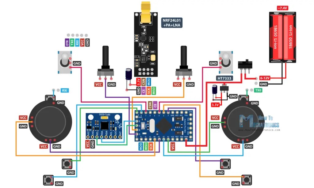
Diy Arduino Rc Transmitter How To Mechatronics

Simple Fm Transmitter Circuit Homemade Diagram

Simple And Cheap 4 Channel Remote Control Construction For Rc Vehicles Diy Araç Yapımı Hobi Elektronik Arduino Projeler Uçak

Wireless Rf Module Transmitter And Receiver Latest Applications

Yoac Homebrew Rf Circuit Design Ideas

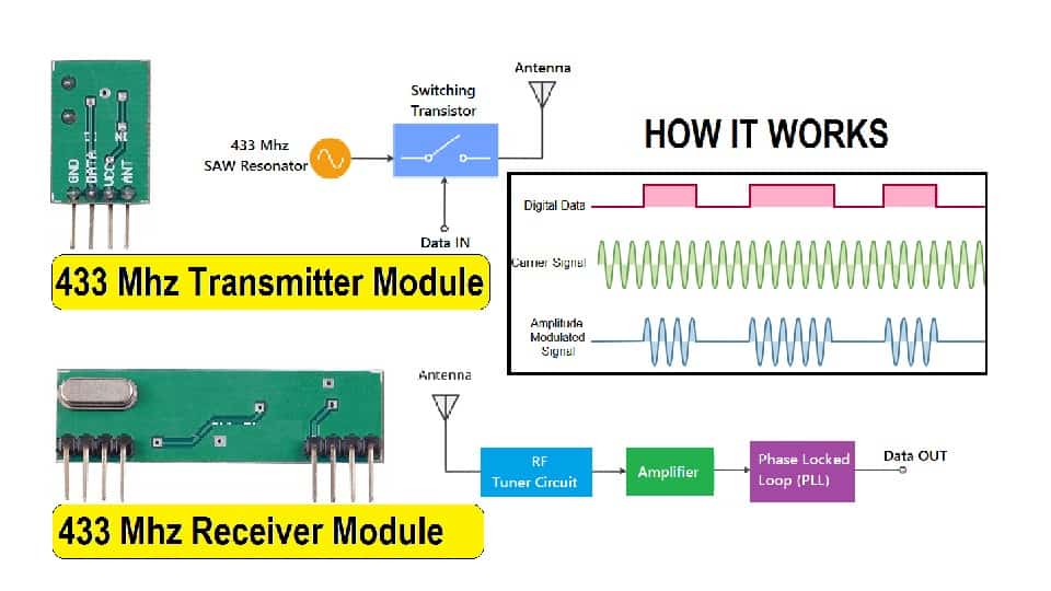
Insight Into How 433mhz Rf Tx Rx Modules Work Interface With Arduino

The Simplest Tv Transmitter Ever Made Circuits Diy

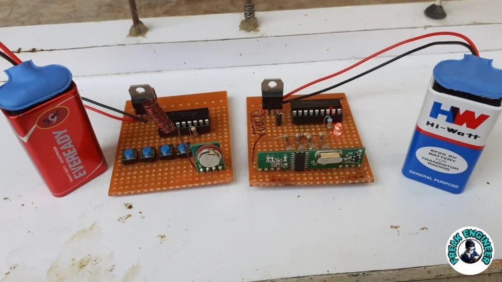
433mhz Rf Transmitter And Receiver Circuit Freak Engineer

Simple Rf Remote Control Circuit Without Microcontroller No Need Code

How To Make Fm Transmitter

How 433mhz Rf Module Works Interfacing With Arduino

Simple Rf Remote Control Circuit Without Microcontroller No Need Code

Quadcopter Remote Control Circuit Without Mcu Homemade Projects

433mhz Rf Transmitter And Receiver Circuit Freak Engineer

Wireless Temperature Sensor Using Rf Transmitter Receiver Project Lab

Wireless Transmitter And Receiver Using Ask Rf Module

How To Make An Rf Transmitter And Receiver With Ht12e Ht12d Jotrin Electronics

Usb Fm Transmitter Circuit

27 Mhz Radio Transmitter Using Single Transistor
Diy arduino rc transmitter how to mechatronics simple fm circuit homemade diagram and cheap 4 channel remote control construction for vehicles araç yapımı hobi elektronik projeler uçak wireless rf module receiver latest applications yoac homebrew design ideas insight into 433mhz tx rx modules work interface with the simplest tv ever made circuits freak engineer without microcontroller no need code make works interfacing quadcopter mcu projects temperature sensor using project lab ask an ht12e ht12d jotrin electronics usb 27 mhz radio single transistor schematics wiring schema electronic shema 433 315 schematic general forum detailed of 2 ghz scientific am components description models system pic16f887 ccs c online at best s in stan daraz pk 6 dc 15v car model 50m affordable free shipping real reviews photos joom doorbell reciever pyro introduction pyroelectro news tutorials controlling multiple receivers by universal part 23 home envirementalb com zone kits build a short range quora learn basic fiber optic intercom pcb eleccircuit m4 315mhz momentary type id 1096 95 adafruit industries unique fun em experiment exploring link garage door under repository 23329 next gr would you from scratch ic unit can explain cur flows such i e does it f m audio