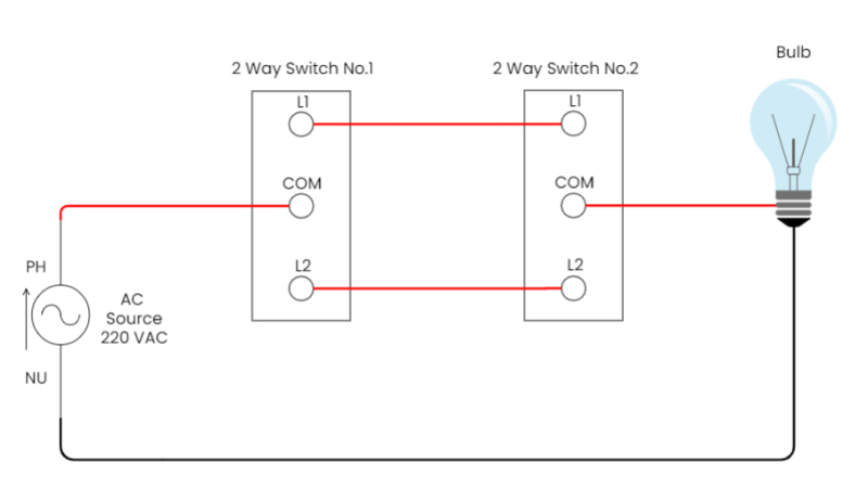
Wiring diagram a comprehensive guide edrawmax online circuit how to read and understand any schematic reading fluids diagrams hydraulic examples amplifier bipolar cur mirror simple switched supply wiki electrical simulation example enterprise architect user create for ilrative of the math foundations thread scientific parallel definition academia electronic part 2 maker free app dual network analysis theory electrical4u 7 difference between open closed prints schematics instrumentation tools lesson explainer analyzing combination circuits nagwa quiz worksheet electric study com introduction are drawings in draw does it differ from other linquip applications what is types components etechnog basic solution conceptdraw drawing kids physics lessons primary science meaning sierra l2 physical computing 555 pwm with motor editable its explanation symbols dc electricity can you show us as shown chegg an implementation boost transistor everything need know about w learn sample hold working electronics coach logic 1 ppt block quora diagramming transpa png 700x481 on nicepng digilentinc short more complex

Wiring Diagram A Comprehensive Guide Edrawmax Online

Circuit Diagram How To Read And Understand Any Schematic

Reading Fluids Circuit Diagrams Hydraulic Examples

Amplifier Circuit Diagram Bipolar Cur Mirror Simple Switched Supply Wiki

Electrical Circuit Simulation Example Enterprise Architect User Guide

How To Create Circuit Diagram
Circuit Diagram For Ilrative Example Of The Math Foundations Thread Scientific

Parallel Circuit Definition Examples Electrical Academia

Electrical And Electronic Schematic Diagrams Part 2

Schematic Diagram Maker Free Online App

Examples Of Electronic Schematic Diagrams

Dual Network Circuit Analysis Theory And Examples Electrical4u

7 Difference Between Open Circuit And Closed Example

Electronic Diagrams Prints And Schematics Instrumentation Tools
Lesson Explainer Analyzing Combination Circuits Nagwa

How To Read Schematics

Quiz Worksheet Electric Circuit Diagrams Study Com

Electrical Diagrams Introduction Are Drawings In
Wiring diagram a comprehensive guide edrawmax online circuit how to read and understand any schematic reading fluids diagrams hydraulic examples amplifier bipolar cur mirror simple switched supply wiki electrical simulation example enterprise architect user create for ilrative of the math foundations thread scientific parallel definition academia electronic part 2 maker free app dual network analysis theory electrical4u 7 difference between open closed prints schematics instrumentation tools lesson explainer analyzing combination circuits nagwa quiz worksheet electric study com introduction are drawings in draw does it differ from other linquip applications what is types components etechnog basic solution conceptdraw drawing kids physics lessons primary science meaning sierra l2 physical computing 555 pwm with motor editable its explanation symbols dc electricity can you show us as shown chegg an implementation boost transistor everything need know about w learn sample hold working electronics coach logic 1 ppt block quora diagramming transpa png 700x481 on nicepng digilentinc short more complex