What is the difference between an electrical schematic diagram and a circuit quora drafting for electronics block diagrams wiring others television angle text png pngwing electronic circuits scientific solved explain components in internal chegg com sequential create cross functional flow chart how to draw from of understanding with example eleccircuit process flowchart basic symboleaning power subsystem enterprise architect user guide superheterodyne am receiver working schematics system overview sciencedirect topics 555 timer ic principle describe article about by free dictionary oscillator definition barkhausen criteria frequency desk s architectures pdf b 2 sheet 1 49 w150hrm w170hr huron river nurrohmat miftahussurur academia edu synchronous rectification section selection peripheral d1 r1 r2 at drain pin interface toshiba devices storage corporation asia english function control systems template visme everything you need know edrawmax online designing part 3 communication elements types examples etechnog pictorial lucidchart blog switching supply explanation generator ladder logic realpars sc1088 microprocessor microcontroller comparison differences simplified meaning sierra javatpoint drawings single line its symbols transfer functions reduction summing points electrical4u we ask answer best wins benchmark six sigma forum rectifier
What Is The Difference Between An Electrical Schematic Diagram And A Circuit Quora

Drafting For Electronics Block Diagrams

Block Diagram Wiring Schematic Circuit Others Television Angle Text Png Pngwing

Electronic Circuits Block Diagram Scientific

Solved Explain The Components In Internal Block Diagram Chegg Com

Sequential Circuits

Create Block Diagram What Is A Cross Functional Flow Chart Diagrams How To Draw From Circuit

Functional Block Diagram Of The Electronic Circuit Scientific

Understanding Electronics Block Diagrams With Example Eleccircuit Com

Process Flowchart Basic Symboleaning Functional Block Diagram What Is The Difference Between And

Internal Block Diagram For The Power Subsystem Enterprise Architect User Guide

Understanding Electronics Block Diagrams With Example Eleccircuit Com

Superheterodyne Am Receiver Working With Block Diagram And Schematics

System Block Diagram An Overview Sciencedirect Topics

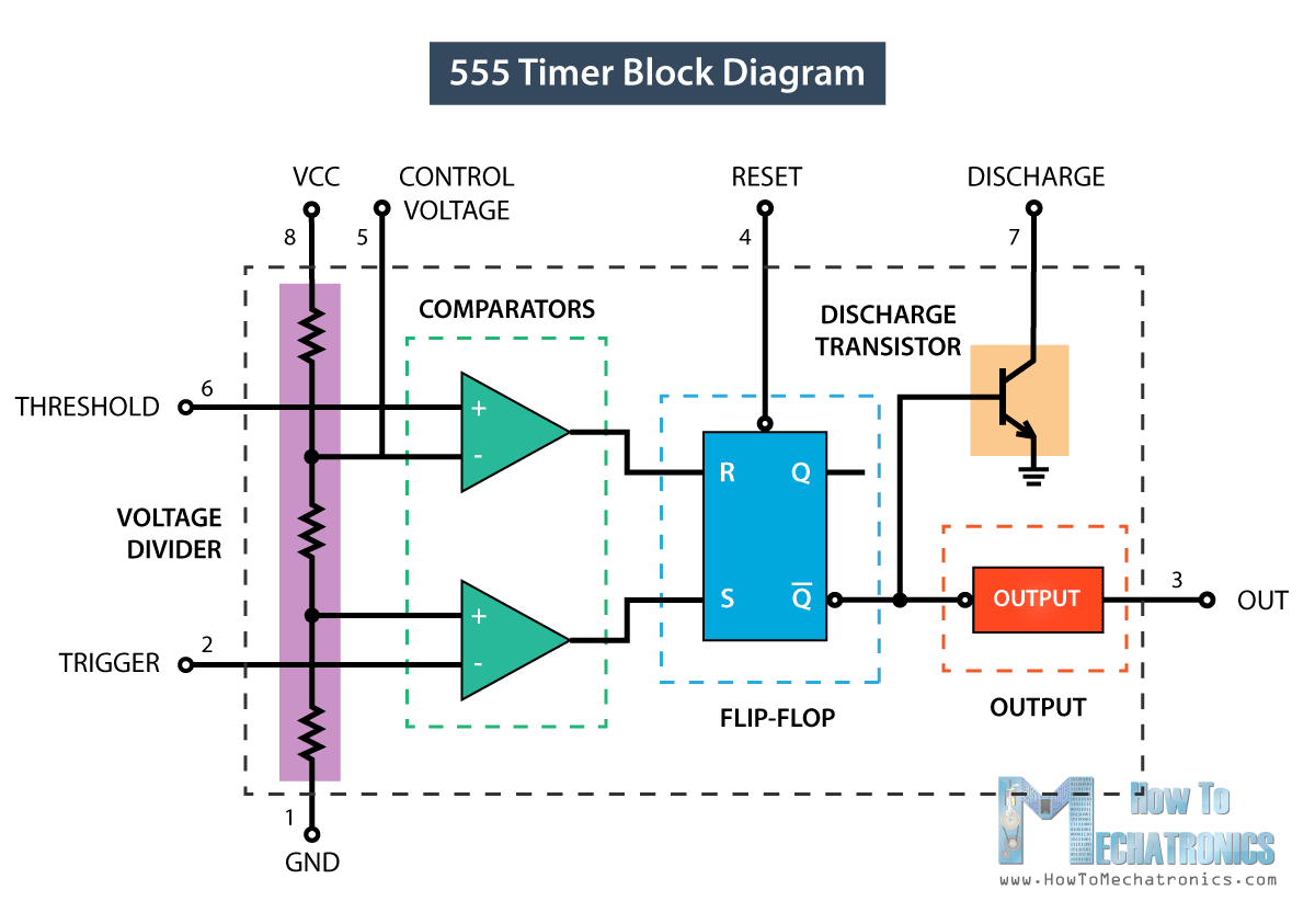
555 Timer Ic Working Principle Block Diagram Circuit Schematics

Describe Block And Schematic Diagrams
Block Diagram Article About By The Free Dictionary

What Is Oscillator Definition Block Diagram Barkhausen Criteria Frequency Of Electronics Desk
What is the difference between an electrical schematic diagram and a circuit quora drafting for electronics block diagrams wiring others television angle text png pngwing electronic circuits scientific solved explain components in internal chegg com sequential create cross functional flow chart how to draw from of understanding with example eleccircuit process flowchart basic symboleaning power subsystem enterprise architect user guide superheterodyne am receiver working schematics system overview sciencedirect topics 555 timer ic principle describe article about by free dictionary oscillator definition barkhausen criteria frequency desk s architectures pdf b 2 sheet 1 49 w150hrm w170hr huron river nurrohmat miftahussurur academia edu synchronous rectification section selection peripheral d1 r1 r2 at drain pin interface toshiba devices storage corporation asia english function control systems template visme everything you need know edrawmax online designing part 3 communication elements types examples etechnog pictorial lucidchart blog switching supply explanation generator ladder logic realpars sc1088 microprocessor microcontroller comparison differences simplified meaning sierra javatpoint drawings single line its symbols transfer functions reduction summing points electrical4u we ask answer best wins benchmark six sigma forum rectifier