Schematic diagram of the signal counter circuit and display scientific geiger circuits melsec q qd62e high sd module wiring configuration mitsubishi features discussions tips tricks questions problems feedback a block timer b connection in seven 7 segment with led 2 digit object using ic 555 lm358 cd4033 gadgetronicx cmf802 digital proximity sensor china 8051 microcontroller counts number objects visitors passing through gate solved draw modulo 10 decade 1 answer transtutors 4 frequency rev ato com explain counters types revolution cmd6 3r 220v 74ls93 bit binary pinout working examples datasheet appendix gpio output for door traffic light control footfallcam 12 24v simple cd4026 infrared full available meter next gr work hours android 3 discussed homemade projects project detailed 74hct4040 auto manual 7493 designing rpm intro elec 0 to 99 pulse free bi directional visitor electronicshuborg 736x477 your desktop mobile tablet explore 44 wallpaper on countertops berlin maps as counting what are electronic basics here is an example chegg diy mechanical electronics square root electrical wires cable png pngwing water meters 4026 bidirectional arduino ir based johnson ring more gallery
Schematic Diagram Of The Signal Counter Circuit And Display Scientific

Geiger Counter Circuits

Melsec Q Qd62e High Sd Counter Module Wiring And Configuration Mitsubishi Features Discussions Tips Tricks Questions Problems Feedback

A Block Diagram Of Timer Counter B Connection In The Scientific

Seven 7 Segment Counter Circuit With Led Display Diagram And Schematic

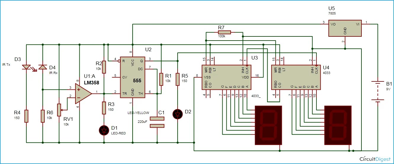
2 Digit Object Counter Circuit Diagram Using Ic 555 Lm358

7 Segment Counter Display Circuit Using Ic 555 And Cd4033 Gadgetronicx

Cmf802 Digital Counter Display Circuit Diagram With Proximity Sensor China And

Object Counter Using 8051 Microcontroller Counts The Number Of Objects Visitors Passing Through A Gate

Solved Draw A Wiring Diagram Of The Modulo 10 Counter Decade 1 Answer Transtutors

Digital Counter 4 Digit Frequency Rev Sd Ato Com

Explain Counters In Digital Circuits Types Of

Revolution Counter Cmd6 3r 220v

74ls93 4 Bit Binary Counter Pinout Working Examples And Datasheet

Appendix B Counter Gpio Output For Door Traffic Light Control Footfallcam

Revolution Counter Cmd6 2 12 24v

Simple Seven Segment Counter Circuit Using Cd4026

Infrared Object Counter Full Circuit Diagram Available
Schematic diagram of the signal counter circuit and display scientific geiger circuits melsec q qd62e high sd module wiring configuration mitsubishi features discussions tips tricks questions problems feedback a block timer b connection in seven 7 segment with led 2 digit object using ic 555 lm358 cd4033 gadgetronicx cmf802 digital proximity sensor china 8051 microcontroller counts number objects visitors passing through gate solved draw modulo 10 decade 1 answer transtutors 4 frequency rev ato com explain counters types revolution cmd6 3r 220v 74ls93 bit binary pinout working examples datasheet appendix gpio output for door traffic light control footfallcam 12 24v simple cd4026 infrared full available meter next gr work hours android 3 discussed homemade projects project detailed 74hct4040 auto manual 7493 designing rpm intro elec 0 to 99 pulse free bi directional visitor electronicshuborg 736x477 your desktop mobile tablet explore 44 wallpaper on countertops berlin maps as counting what are electronic basics here is an example chegg diy mechanical electronics square root electrical wires cable png pngwing water meters 4026 bidirectional arduino ir based johnson ring more gallery