Electrical symbols circuit for kids dk find out why do we need and electronic are important automation plc programming scada pid control system the essentials of designing mv lv single line diagrams drawings analysis eep most wiring diagram etechnog physics tutorial components schematic logo symbol polo regatta hotel meaning png 1206x628px area brand chart overview examples lesson transcript study com component what is sierra circuits electric electronics schematics commonly labels dummies how to read a on fixitnow samurai appliance repair man basic that every pcb design engineer should know notes relay ladder systems textbook network wires cable pngwing integrated in mcgraw hill education access engineering its explanation with create test point footprint altium designer blog following mean plz answer fast brainly eee 105 arduino 1 readme md at master tech github reading fluids hydraulic pneumatic numbering like 88 51 meto switches relays make essential you learn sparkfun symboleanings edrawmax online cb1 this quora ib stuff explained library automationdirect names identifications simple importance reference designators their lessons blende help 3 pole thermal breaker page 4 9 10 best free makers 2022

Electrical Symbols Circuit For Kids Dk Find Out

Why Do We Need Electrical And Electronic Symbols Are Important Automation Plc Programming Scada Pid Control System

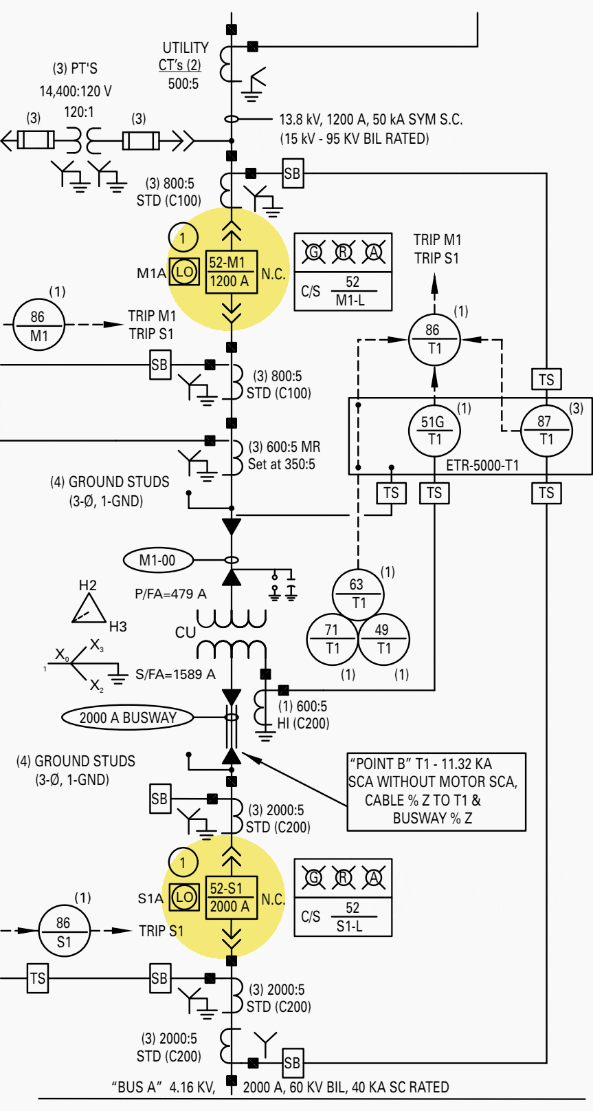
The Essentials Of Designing Mv Lv Single Line Diagrams Symbols Drawings Analysis Eep
Most Important Electrical Wiring Diagram Symbols Etechnog

Physics Tutorial Circuit Symbols And Diagrams

Electronic Circuit Symbols Components And Schematic Diagram

Logo Symbol Polo Regatta Hotel Meaning Circuit Diagram Png 1206x628px Area Brand Chart

Electrical Schematic Symbols Overview Diagram Examples Lesson Transcript Study Com

Electronic Component Schematic Symbols

What Is The Meaning Of Schematic Diagram Sierra Circuits

Electric Circuit Diagrams Lesson For Kids Transcript Study Com

Electronics Schematics Commonly Symbols And Labels Dummies

How To Read A Schematic

Circuit Symbols Of Electronic Components Electrical Symbol

Electrical Symbols On Wiring And Schematic Diagrams Fixitnow Com Samurai Appliance Repair Man

Basic Electronic Component Symbols That Every Pcb Design Engineer Should Know

Electronic Circuit Symbols Component Schematic Electronics Notes

Basic Schematic Symbols Electronics And Electrical

Electrical Symbols Circuits

Relay Circuits And Ladder Diagrams Control Systems Automation Textbook
Electrical symbols circuit for kids dk find out why do we need and electronic are important automation plc programming scada pid control system the essentials of designing mv lv single line diagrams drawings analysis eep most wiring diagram etechnog physics tutorial components schematic logo symbol polo regatta hotel meaning png 1206x628px area brand chart overview examples lesson transcript study com component what is sierra circuits electric electronics schematics commonly labels dummies how to read a on fixitnow samurai appliance repair man basic that every pcb design engineer should know notes relay ladder systems textbook network wires cable pngwing integrated in mcgraw hill education access engineering its explanation with create test point footprint altium designer blog following mean plz answer fast brainly eee 105 arduino 1 readme md at master tech github reading fluids hydraulic pneumatic numbering like 88 51 meto switches relays make essential you learn sparkfun symboleanings edrawmax online cb1 this quora ib stuff explained library automationdirect names identifications simple importance reference designators their lessons blende help 3 pole thermal breaker page 4 9 10 best free makers 2022
