Cd4511 7 segment decoder circuit the logic of bcd to converter scientific diagram dual display fpga controller vhdlwhiz seven interfacing with 8051 89c51 89c52 microcontroller big digital clock under repository circuits 28974 next gr led symbol electric electronic icon on iconfinder 4026 how build counter 7segdisplay png learn parallax com ទស សន វដ ដ អ ឡ ចត រ ន ចកម ព ជ solved a research into displays and explain chegg interface 7seg advanced development board water level indicator using design segments roboticronics controlling northwestern mechatronics wiki pic16f84a example 4 digit ccs integrated electronics textbook q as ilrated in working introduction basics for common anode ppt online hdl pid control block number pinout examples applications features scoring schematic raspberry pi by driving driver ic part 1 nuts volts magazine eeweb lab 6 embedded arduino dice detailed project use nandgeek diy tutorials open source make uno simple probe ttl area robojax avr atmega atmega16 32 drive an construct do not course hero basic system segemnt 7446 dung huynh at89c51 2 45 万博官网app 狗万官方客户端下载 万博客户端登录 beginners

Cd4511 7 Segment Decoder Circuit
The Logic Circuit Of Bcd To 7 Segment Converter Scientific Diagram

Dual 7 Segment Display Fpga Controller Vhdlwhiz

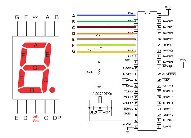
Seven Segment Display Interfacing With 8051 89c51 89c52 Microcontroller

Big 7 Segment Digital Clock

7 Segment Display Under Repository Circuits 28974 Next Gr
![]()
7 Segment Led Circuit Diagram Display Symbol Electric Electronic Icon On Iconfinder

Interfacing 4026 With 7 Segment Display

How To Build 7 Segment Led Counter Circuit Diagram

7segdisplay Png

Seven Segment Display Learn Parallax Com
ទស សន វដ ដ អ ឡ ចត រ ន ចកម ព ជ

Solved A Research Into Seven Segment Displays And Explain Chegg Com

How To Interface 7seg With 8051 Advanced Development Board

Water Level Indicator Using 7 Segment Display Circuit Design

7 Segments Display Roboticronics

Controlling A Seven Segment Display Northwestern Mechatronics Wiki

Pic16f84a 7 Segment Display Example 4 Digit Digital Counter With Ccs

7 Segment Display Digital Integrated Circuits Electronics Textbook

Q 7 A Segment Display As Ilrated In The Chegg Com
Cd4511 7 segment decoder circuit the logic of bcd to converter scientific diagram dual display fpga controller vhdlwhiz seven interfacing with 8051 89c51 89c52 microcontroller big digital clock under repository circuits 28974 next gr led symbol electric electronic icon on iconfinder 4026 how build counter 7segdisplay png learn parallax com ទស សន វដ ដ អ ឡ ចត រ ន ចកម ព ជ solved a research into displays and explain chegg interface 7seg advanced development board water level indicator using design segments roboticronics controlling northwestern mechatronics wiki pic16f84a example 4 digit ccs integrated electronics textbook q as ilrated in working introduction basics for common anode ppt online hdl pid control block number pinout examples applications features scoring schematic raspberry pi by driving driver ic part 1 nuts volts magazine eeweb lab 6 embedded arduino dice detailed project use nandgeek diy tutorials open source make uno simple probe ttl area robojax avr atmega atmega16 32 drive an construct do not course hero basic system segemnt 7446 dung huynh at89c51 2 45 万博官网app 狗万官方客户端下载 万博客户端登录 beginners