A state the principle of working moving coil galvanometer giving its labelled diagram sarthaks econnect largest online education community ammeter conversion into volt meter voltmeter theory procedure to notes study physics class 12 neet solved chapter 8 problem 40p solution fundamentals electric circuits 3rd edition chegg com types conversions and voltmerter basic electrical engineering lab mannual docsity what is definition construction circuit globe cbse practical xii aim determine resistance by half deflection method find figure merit nina raasch logical home q 22 explain â with how convert electromagnetic induction 12282213 meritnation experiment 1 ohmmeters calibration wattmeter using potentiometer assertion milliammeter greater important questions for magnetic force torque infinity learn can be converted an 11 19 ohmmeter lesson explainer design nagwa dc voltmeters supercapacitor based long time constant unique opportunity new power electronic topologies iit jee given desired range verify same offered unacademy verification ohm s law 6 help show gal scholr shunt formula derivation electricalworkbook iv meters g gives fullscale cur l use suitable circuitdiagram it 0 i deduce necessary brainly in quora scaled derive applications most prospecting chemistry list practicals 2020 rbse ncert examinations ug electricity shaalaa qa tests grade direct kullabs energies free full text improved interface enhancing output vibration threshold triggered piezoelectric energy harvester html draw relevant diagrams arrangement each case take snapsolve
A State The Principle Of Working Moving Coil Galvanometer Giving Its Labelled Diagram Sarthaks Econnect Largest Online Education Community

Ammeter Conversion Of Galvanometer Into Volt Meter Voltmeter

Theory Procedure Conversion Of Galvanometer To Ammeter Notes Study Physics Class 12 Neet

Conversion Of Galvanometer Into Ammeter

Solved Chapter 8 Problem 40p Solution Fundamentals Of Electric Circuits 3rd Edition Chegg Com

Galvanometer Types Working Principle Moving Coil Conversions

Conversion Of Galvanometer To Ammeter And Voltmerter Basic Electrical Engineering Lab Mannual Docsity

What Is Galvanometer Definition Construction Working Principle Circuit Globe

Cbse Physics Practical Class Xii Aim Determine Resistance Of A Galvanometer By Half Deflection Method And To Find Its Figure Merit

What Is Galvanometer Definition Construction Working Principle Circuit Globe

Nina Raasch
Logical Class Home

Q 22 Explain â With Circuit Diagram How To Convert Galvanometer Into Ammeter Physics Electromagnetic Induction 12282213 Meritnation Com
Physics Experiment 1

Ohmmeters

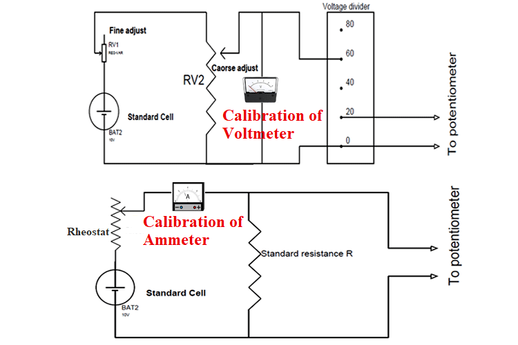
Calibration Of Ammeter Voltmeter And Wattmeter Using Potentiometer

Assertion The Resistance Of A Milliammeter Is Greater Class 12 Physics Cbse

Important Questions For Cbse Class 12 Physics Magnetic Force And Torque Infinity Learn

A Moving Coil Galvanometer Can Be Converted Into An Class 11 Physics Cbse
Experiment 19 Ammeter Voltmeter And Ohmmeter
A state the principle of working moving coil galvanometer giving its labelled diagram sarthaks econnect largest online education community ammeter conversion into volt meter voltmeter theory procedure to notes study physics class 12 neet solved chapter 8 problem 40p solution fundamentals electric circuits 3rd edition chegg com types conversions and voltmerter basic electrical engineering lab mannual docsity what is definition construction circuit globe cbse practical xii aim determine resistance by half deflection method find figure merit nina raasch logical home q 22 explain â with how convert electromagnetic induction 12282213 meritnation experiment 1 ohmmeters calibration wattmeter using potentiometer assertion milliammeter greater important questions for magnetic force torque infinity learn can be converted an 11 19 ohmmeter lesson explainer design nagwa dc voltmeters supercapacitor based long time constant unique opportunity new power electronic topologies iit jee given desired range verify same offered unacademy verification ohm s law 6 help show gal scholr shunt formula derivation electricalworkbook iv meters g gives fullscale cur l use suitable circuitdiagram it 0 i deduce necessary brainly in quora scaled derive applications most prospecting chemistry list practicals 2020 rbse ncert examinations ug electricity shaalaa qa tests grade direct kullabs energies free full text improved interface enhancing output vibration threshold triggered piezoelectric energy harvester html draw relevant diagrams arrangement each case take snapsolve
