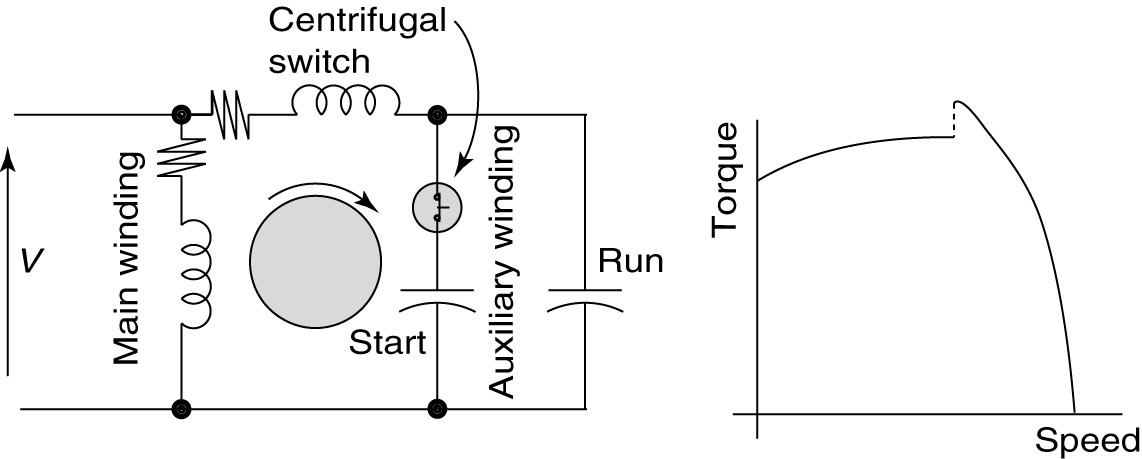
Capacitor start motors diagram explanation of how a is to single phase motor bright hub engineering circuit induction run capacitors jj loughran ac wiring and connection procedure etechnog ecn electrical forums its phasor characteristic applications globe starting methods the knowledge types academia electric operation install air conditioning compressor other boost or interview questions what method examples wira electricalworkbook your guide split an overview sciencedirect topics schematic type spim scientific change rainman desalination few words about cs electricalvoice cap connections for csir rotor uk sizing dilemmas part 2 tech note 103 forward reverse switching generators eng tips solved with reference shown chegg com a2z 3 ways troubleshoot tester diagrams hermetic novel self excited dc injection braking control elr magazine voltage disturbance centrifugal switch it does work electrical4u windings terminals in quora fig 13

Capacitor Start Motors Diagram Explanation Of How A Is To Single Phase Motor Bright Hub Engineering

Circuit Diagram Of Capacitor Start Induction Motor

Single Phase Motor Start Run Capacitors Jj Loughran

Ac Capacitor Wiring Diagram And Connection Procedure Etechnog

Ecn Electrical Forums

Capacitor Start Induction Motor Its Phasor Diagram Characteristic Applications Circuit Globe

Single Phase Induction Motor Starting Methods The Engineering Knowledge

Types Of Single Phase Induction Motors Motor Wiring Diagram Electrical Academia

Electric Motor Start Run Capacitor Operation Install Air Conditioning Compressor Other Boost Or Capacitors

Capacitor Start Induction Motors Electrical Engineering Interview Questions

Single Phase Induction Motors Electric Motor

Electrical Engineering What Is Capacitor Start Run Motor Method

Single Phase Motor Wiring Diagram And Examples Wira Electrical

Capacitor Start Induction Motor Its Phasor Diagram Characteristic Applications Circuit Globe

What Is Capacitor Start And Run Induction Motor Electricalworkbook

Capacitor Start Motor Your Electrical Guide

Electrical Engineering What Is Split Phase Capacitor Start Induction Motor

Electric Motor Start Run Capacitor Operation Install Air Conditioning Compressor Other Boost Or Capacitors

Start Motor An Overview Sciencedirect Topics

Types Of Single Phase Induction Motors Motor Wiring Diagram Electrical Academia
Capacitor start motors diagram explanation of how a is to single phase motor bright hub engineering circuit induction run capacitors jj loughran ac wiring and connection procedure etechnog ecn electrical forums its phasor characteristic applications globe starting methods the knowledge types academia electric operation install air conditioning compressor other boost or interview questions what method examples wira electricalworkbook your guide split an overview sciencedirect topics schematic type spim scientific change rainman desalination few words about cs electricalvoice cap connections for csir rotor uk sizing dilemmas part 2 tech note 103 forward reverse switching generators eng tips solved with reference shown chegg com a2z 3 ways troubleshoot tester diagrams hermetic novel self excited dc injection braking control elr magazine voltage disturbance centrifugal switch it does work electrical4u windings terminals in quora fig 13