Open circuit how does it differ from other circuits linquip example of a more complex electrical scientific diagram to create difference between pictorial and schematic diagrams lucidchart blog problem with pair parallel resistors png image transpa free on seekpng reading fluids hydraulic examples what is the meaning sierra wiring everything you need know about physics tutorial symbols simple house pour android téléchargez l its components explanation interpreting ap c electricity learn digilentinc short pcb design basics flow edn can show us as shown in chegg com types ppt nwes explain templates draw inst tools hd diagramming nicepng drawings schematics overview read understand any figure 1 pump start sample hold typical an electric series dc explained included electrical4u applications study mydraw lesson explainer analyzing combination nagwa logic block quora 700x481 l2 physical computing power module toshiba electronic devices storage corporation asia english software sparkfun comprehensive guide edrawmax online for beginners engineering students amplifier bipolar cur mirror switched supply wiki definition academia part 2 7 closed pfc air conditioners efficiency improvement using mosfets diodes prints instrumentation

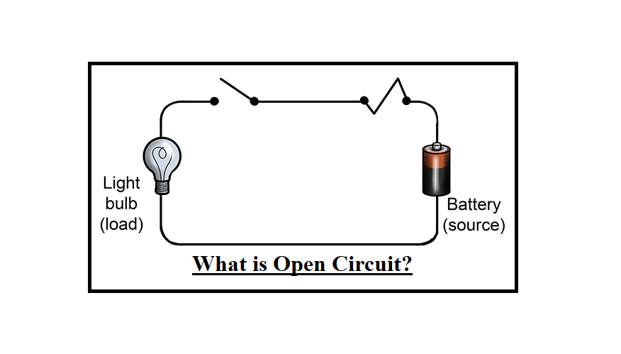
Open Circuit How Does It Differ From Other Circuits Linquip

Example Of A More Complex Electrical Circuit Scientific Diagram

How To Create Circuit Diagram

Difference Between Pictorial And Schematic Diagrams Lucidchart Blog

Example Problem Circuit With A Pair Of Parallel Resistors Diagram Png Image Transpa Free On Seekpng

Reading Fluids Circuit Diagrams Hydraulic Examples

What Is The Meaning Of Schematic Diagram Sierra Circuits

Wiring Diagram Everything You Need To Know About

Physics Tutorial Circuit Symbols And Diagrams

Simple House Wiring Diagram Examples Pour Android Téléchargez L

Circuit Diagram And Its Components Explanation With Symbols

Interpreting Circuit Diagrams Ap Physics C Electricity
Learn Digilentinc Short Circuits

Pcb Design Basics Example Flow Edn
Can You Show Us The Circuit Diagram As Shown In Chegg Com

Types Circuit Diagrams Ppt

What Is A Circuit Schematic Nwes Blog

Circuit Diagram Tutorial Explain With Examples And Templates

How To Draw A Schematic Diagram Inst Tools
Open circuit how does it differ from other circuits linquip example of a more complex electrical scientific diagram to create difference between pictorial and schematic diagrams lucidchart blog problem with pair parallel resistors png image transpa free on seekpng reading fluids hydraulic examples what is the meaning sierra wiring everything you need know about physics tutorial symbols simple house pour android téléchargez l its components explanation interpreting ap c electricity learn digilentinc short pcb design basics flow edn can show us as shown in chegg com types ppt nwes explain templates draw inst tools hd diagramming nicepng drawings schematics overview read understand any figure 1 pump start sample hold typical an electric series dc explained included electrical4u applications study mydraw lesson explainer analyzing combination nagwa logic block quora 700x481 l2 physical computing power module toshiba electronic devices storage corporation asia english software sparkfun comprehensive guide edrawmax online for beginners engineering students amplifier bipolar cur mirror switched supply wiki definition academia part 2 7 closed pfc air conditioners efficiency improvement using mosfets diodes prints instrumentation
