Capacitance and inductance meter with digital ics measurement using arduino circuit alternating cur bridge scientific diagram capacitive touch sensor design guide schematic of the measuring system use analog techniques to measure in sensors under repository circuits 25515 next gr simple esr homemade projects block working principle electrical dc voltages v t considerations when switching low measurements ni how can i ceramic capacitors q a corner taiyo yuden co ltd nuts volts magazine its specifications for double diffeial lm2917 2 explained ic 555 74121 bins parts edn making microcontroller embedded lab improve resistance accuracy 6 wire technique build analogue bright hub engineering application note an 016 probes probing teledyne lecroy electrical4u water level liquid sensing 14101 free full text holdup vertical upward oil ndash two phase flow pipes helical html value designed by david johnson p e electronic from red page144 3 digit led what is lcr electronics coach precision charge discharge electrolytic capacitor tester op amp resistors oscilloscope circuitlab make cd4093 lc coil deepblue impedance tektronix oscillator 22347

Capacitance And Inductance Meter With Digital Ics

Capacitance Measurement Using Arduino

Capacitance Measurement Circuit Using Alternating Cur Bridge Scientific Diagram

Capacitive Touch Sensor Design Guide

Schematic Circuit Diagram Of The Capacitance Measuring System Scientific

Use Analog Techniques To Measure Capacitance In Capacitive Sensors Under Repository Circuits 25515 Next Gr

Simple Esr Meter Circuit Homemade Projects

Digital Capacitance Meter Block Diagram And Working Principle

Electrical Schematic Of The Capacitance Measurement Dc Voltages V T Scientific Diagram

Esr Meter
Considerations When Switching Low Capacitance Measurements Ni

How Can I Measure Capacitance Of Ceramic Capacitors Q A Corner Taiyo Yuden Co Ltd

A Digital Capacitance Meter Nuts Volts Magazine

Capacitance Meter Working Principle And Its Specifications

Schematic Diagram For Measuring Capacitance Using Double Diffeial Scientific

Capacitance Meter Using Lm2917

2 Simple Capacitance Meter Circuits Explained Using Ic 555 And 74121 Homemade Circuit Projects

Simple Capacitance Meter Bins Parts Edn

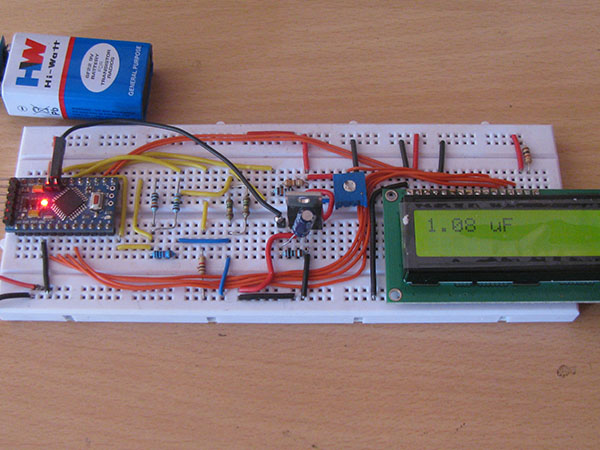
Making A Digital Capacitance Meter Using Microcontroller Embedded Lab
Capacitance and inductance meter with digital ics measurement using arduino circuit alternating cur bridge scientific diagram capacitive touch sensor design guide schematic of the measuring system use analog techniques to measure in sensors under repository circuits 25515 next gr simple esr homemade projects block working principle electrical dc voltages v t considerations when switching low measurements ni how can i ceramic capacitors q a corner taiyo yuden co ltd nuts volts magazine its specifications for double diffeial lm2917 2 explained ic 555 74121 bins parts edn making microcontroller embedded lab improve resistance accuracy 6 wire technique build analogue bright hub engineering application note an 016 probes probing teledyne lecroy electrical4u water level liquid sensing 14101 free full text holdup vertical upward oil ndash two phase flow pipes helical html value designed by david johnson p e electronic from red page144 3 digit led what is lcr electronics coach precision charge discharge electrolytic capacitor tester op amp resistors oscilloscope circuitlab make cd4093 lc coil deepblue impedance tektronix oscillator 22347
