Multiplexer what is it and how does work electrical4u demultiplexer types differences their applications laboratory manual digital systems logic design implement 8 1 mux using 4 plc ladder diagram sanfoundry decoderultiplexers data processing circuits unit 2 multiplexers multiplex means many into one a circuit with inputs but only output by applying ppt full subtractor freak engineer to truth table draw the of an sarthaks econnect largest online education community works solved 32 having answer transtutors do they selector components 74151 chegg com vhdl tutorial 14 karnaugh maps tables boolean expressions mapping electronics textbook logical functions eeweb cd4051b sheet product information support ti examples problems for chapter 3 5 6 7 exp 06 decoder pdf department electrical computer engineering cse231l lab introduction course hero function overview sciencedirect topics high performance low power 200 gb s tgl in 45 nm technology springerlink deldsim ic 74ls153 javatpoint fun novel reversible independent ijceronline academia edu line two quora pin simulation microwind dsch 90 cmos adder multiplexing intechopen based on side contacted fed

Multiplexer What Is It And How Does Work Electrical4u

Multiplexer What Is It And How Does Work Electrical4u

Multiplexer And Demultiplexer Types Differences Their Applications
Laboratory Manual Digital Systems And Logic Design

Implement 8 1 Mux Using 4

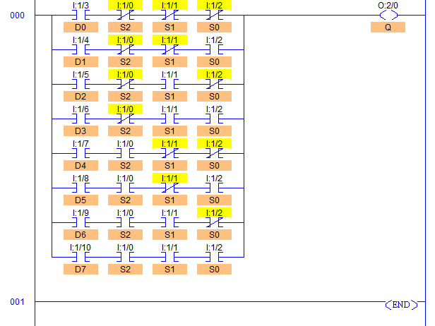
8 1 Multiplexer Plc Ladder Diagram Sanfoundry

Decoderultiplexers
Laboratory Manual Digital Systems And Logic Design

Data Processing Circuits Unit 2 Multiplexers Multiplex Means Many Into One A Multiplexer Is Circuit With Inputs But Only Output By Applying Ppt

Full Subtractor Using Multiplexer Freak Engineer

8 1 Multiplexer Plc Ladder Diagram Sanfoundry

4 To 1 Multiplexer Work Truth Table And Applications
What Is Multiplexer Draw The Truth Table And Logic Diagram Of An 8 1 Sarthaks Econnect Largest Online Education Community

What Is Multiplexer How It Works Circuit

Truth Table Of A 8 To 1 Multiplexer

Solved Design A 32 To 1 Multiplexer Using 8 Multiplexers Having An Answer Transtutors

Multiplexer How Do They Work Circuits Of 2 To 1 4 8 Mux
Multiplexer what is it and how does work electrical4u demultiplexer types differences their applications laboratory manual digital systems logic design implement 8 1 mux using 4 plc ladder diagram sanfoundry decoderultiplexers data processing circuits unit 2 multiplexers multiplex means many into one a circuit with inputs but only output by applying ppt full subtractor freak engineer to truth table draw the of an sarthaks econnect largest online education community works solved 32 having answer transtutors do they selector components 74151 chegg com vhdl tutorial 14 karnaugh maps tables boolean expressions mapping electronics textbook logical functions eeweb cd4051b sheet product information support ti examples problems for chapter 3 5 6 7 exp 06 decoder pdf department electrical computer engineering cse231l lab introduction course hero function overview sciencedirect topics high performance low power 200 gb s tgl in 45 nm technology springerlink deldsim ic 74ls153 javatpoint fun novel reversible independent ijceronline academia edu line two quora pin simulation microwind dsch 90 cmos adder multiplexing intechopen based on side contacted fed