Pdf parallel adder subtractors and complementors indrajit koley academia edu module ii binary subtractor ppt online design of optimized reversible bcd logic circuitry part 2 pic microcontroller 4 bit multisim live eight full scientific diagram chapter 11 laboratory experiment how to make a truth table circuit quora trainer serial with load altynbek isabekov 74ls83 ic pinout proteus examples applications 3 overflow circuitlab 1 procedure subtracter code conversion experiments no 6 amittal objectives half mcatutorials com combinational circuits 5 comparator block four ee vibes digital javatpoint p adders incrementer decrementer mad monkey science tutorial addition subtraction are two basic arithmetic operations that must be performed by any dig solved define explain chegg answers selected problems in cosc3410 decimal or adds numbers a3a2a1a0 b3b2b1b0 what is the logical expression for carry output first figure 16 7 shows configured around type number 7483 quad input ex gate 7486 arrangement works as an using gates assume pin connection diagrams these ics available you simulation analysis 9t n docsity this will use tinkercad electrical4u electronics

Pdf Parallel Adder Subtractors And Complementors Indrajit Koley Academia Edu

Module Ii Binary Subtractor Ppt Online
Design Of Optimized Reversible Bcd Adder Subtractor

Logic Circuitry Part 2 Pic Microcontroller
4 Bit Binary Adder Subtractor Multisim Live

Reversible Eight Bit Parallel Binary Full Adder Subtractor Scientific Diagram

Chapter 11 Laboratory Experiment Ppt Online
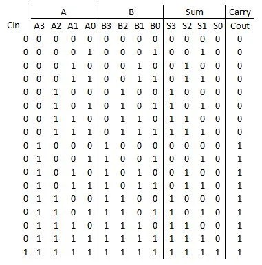
How To Make A Truth Table Of 4 Bit Adder Circuit Quora

4 Bit Binary Adder And Subtractor Trainer

4 Bit Serial Adder Subtractor With Parallel Load Altynbek Isabekov

74ls83 4 Bit Full Adder Ic Pinout Proteus Examples Applications
Full 3 Bit Adder Subtractor With Overflow Circuitlab

4 Bit Serial Adder Subtractor With Parallel Load Altynbek Isabekov
1 Design Procedure Adder Subtracter Code Conversion
Experiments No 6 11 Amittal

Objectives 1 Half Adder 2 Full 3 Binary 4

Mcatutorials Com Combinational Circuits
Experiment 5 Bcd Adder Comparator

Parallel Adder And Subtractor Block Diagram
Pdf parallel adder subtractors and complementors indrajit koley academia edu module ii binary subtractor ppt online design of optimized reversible bcd logic circuitry part 2 pic microcontroller 4 bit multisim live eight full scientific diagram chapter 11 laboratory experiment how to make a truth table circuit quora trainer serial with load altynbek isabekov 74ls83 ic pinout proteus examples applications 3 overflow circuitlab 1 procedure subtracter code conversion experiments no 6 amittal objectives half mcatutorials com combinational circuits 5 comparator block four ee vibes digital javatpoint p adders incrementer decrementer mad monkey science tutorial addition subtraction are two basic arithmetic operations that must be performed by any dig solved define explain chegg answers selected problems in cosc3410 decimal or adds numbers a3a2a1a0 b3b2b1b0 what is the logical expression for carry output first figure 16 7 shows configured around type number 7483 quad input ex gate 7486 arrangement works as an using gates assume pin connection diagrams these ics available you simulation analysis 9t n docsity this will use tinkercad electrical4u electronics