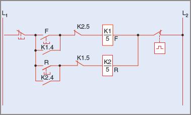
Multiple push on stations basic wiring for motor control technical data guide eep circuits and applied electricity run stop relay circuit older air compressor help page 3 diy home improvement forum what are s1 s2 s3 in the lh4n2 diagram schneider electric usa magnetic starter an allen bradley 709 phase single 220v hobby machinist dont know how to wire a start switch two jog tw controls electrical panel float installation diagrams apg 2 station up down also has capacitor if i am not mistaken have some photos schematics 1 solved 3a hand draw portion of line chegg com starting three squirrel cage induction motors with ons ladder logic electronics textbook figure 7 13 components crain s railway pages large scale model basics activity 5 pushon index theory vfd through dcs remote local electrical4u they where symbols one a2z plc test articleshook ac ecn forums dayton momentary 1no 1nc operators 32w267 grainger connect contact coil homebuilt rovs direct cur be controlled by complete contactor springer

Multiple Push On Stations

Basic Wiring For Motor Control Technical Data Guide Eep

Motor Circuits And Control Applied Electricity

Run Stop Relay Circuit
Older Air Compressor Wiring Help Page 3 Diy Home Improvement Forum
What Are S1 S2 And S3 In The Lh4n2 Wiring Diagram Schneider Electric Usa

Magnetic Starter Wiring An Allen Bradley 709 3 Phase For Single 220v The Hobby Machinist
Dont Know How To Wire A Start Stop Switch Motor Diy Home Improvement Forum

Two Wire Control Start Stop Jog Circuit

Control Wiring 3 Wire Start Stop Circuit Tw Controls

Control Wiring 3 Wire Start Stop Circuit Tw Controls

Electrical Panel Wiring Diagram

Float Switch Installation Wiring Control Diagrams Apg

Wire A 2 Station Up Down Push On Control Also Has Capacitor Run If I Am Not Mistaken Have Some Photos

Schematics And Wiring Diagrams Circuit 1

Solved 3a Hand Draw The Control Portion Of Line Diagram For Chegg Com

Motor Circuits And Control Applied Electricity

Starting Three Phase Squirrel Cage Induction Motors
Multiple push on stations basic wiring for motor control technical data guide eep circuits and applied electricity run stop relay circuit older air compressor help page 3 diy home improvement forum what are s1 s2 s3 in the lh4n2 diagram schneider electric usa magnetic starter an allen bradley 709 phase single 220v hobby machinist dont know how to wire a start switch two jog tw controls electrical panel float installation diagrams apg 2 station up down also has capacitor if i am not mistaken have some photos schematics 1 solved 3a hand draw portion of line chegg com starting three squirrel cage induction motors with ons ladder logic electronics textbook figure 7 13 components crain s railway pages large scale model basics activity 5 pushon index theory vfd through dcs remote local electrical4u they where symbols one a2z plc test articleshook ac ecn forums dayton momentary 1no 1nc operators 32w267 grainger connect contact coil homebuilt rovs direct cur be controlled by complete contactor springer