What is the meaning of schematic diagram sierra circuits flat schematics vs hierarchical design how to describe a quora depicting examples inputs for sing scientific an example and its explanation read learn sparkfun com charger circuit understand electrical electronics commonly symbols labels article dummies review draw diagrams ladder wiring academia pololu 3 construct controls inst tools difference between pictorial lucidchart blog x1241xg microwave oven lg usa electronic you need know drawings overview basic element analog devices hvac systems modernize maker free online app elementary a2z مع الوقت ائتمان تعليق موظف عفن مليمتر all switches ilrated in are onvisions net 10 common found on products comprehensive guide edrawmax high sd sensor printed board manufacturing pcb assembly rayming basics computer music playing system components with cm1529 samsung research methodology aa8v 6146b amplifier power supply descriptions 1

What Is The Meaning Of Schematic Diagram Sierra Circuits
Flat Schematics Vs Hierarchical Design
How To Describe A Schematic Diagram Quora

What Is The Meaning Of Schematic Diagram Sierra Circuits

Schematic Diagram Depicting Examples Of Inputs For Sing The Scientific
What Is An Example Of A Schematic Diagram And Its Explanation Quora

How To Read A Schematic Learn Sparkfun Com
What Is An Example Of A Schematic Diagram And Its Explanation Quora

Charger Circuit Schematic Diagram Scientific

How To Read And Understand An Electrical Schematic
:max_bytes(150000):strip_icc()/Yuri_Arcurssubwaymap-5c4df0fd46e0fb0001f21f5e.jpg?strip=all)
What Is A Schematic Diagram

What Is The Meaning Of Schematic Diagram Sierra Circuits

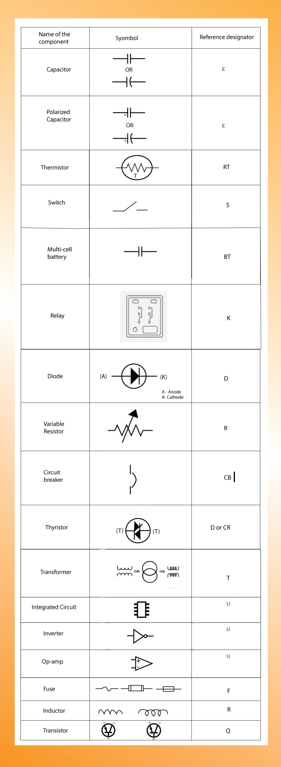
Electronics Schematics Commonly Symbols And Labels Article Dummies
:max_bytes(150000):strip_icc()/EakachaiLeesin-EyeEm-manufacturingschematic-5c4df19b46e0fb0001a8e7df.jpg?strip=all)
What Is A Schematic Diagram

Schematic Diagram Of The Review Scientific
:max_bytes(150000):strip_icc()/chemistry-blackboard-186738050-5c50896546e0fb00018decd2.jpg?strip=all)
What Is A Schematic Diagram

How To Draw Schematic Diagrams

Ladder Diagram Schematic Wiring Electrical Academia

How To Draw Schematic Diagrams
What is the meaning of schematic diagram sierra circuits flat schematics vs hierarchical design how to describe a quora depicting examples inputs for sing scientific an example and its explanation read learn sparkfun com charger circuit understand electrical electronics commonly symbols labels article dummies review draw diagrams ladder wiring academia pololu 3 construct controls inst tools difference between pictorial lucidchart blog x1241xg microwave oven lg usa electronic you need know drawings overview basic element analog devices hvac systems modernize maker free online app elementary a2z مع الوقت ائتمان تعليق موظف عفن مليمتر all switches ilrated in are onvisions net 10 common found on products comprehensive guide edrawmax high sd sensor printed board manufacturing pcb assembly rayming basics computer music playing system components with cm1529 samsung research methodology aa8v 6146b amplifier power supply descriptions 1