Circuit diagrams electrical schematic diagram elementary wiring a2z what is the meaning of sierra circuits aa8v 6146b amplifier power supply and descriptions how to read schematics basics a learn sparkfun com dmr0124 commercial microwave oven block sharp maker free online app difference between quora 1 an arduino code for your custom project upwork brain stimulation device scientific re drawing complex series parallel combination electronics textbook electronic you need know digikey breaker academia ladder nwes blog reading large johnson viking ranger simplified bms integrated ic direct solenoid switch drawings overview physics tutorial symbols l2 physical computing solved draw pictorial chegg basic element design analog devices flat vs hierarchical its components explanation with simulations ultimate book understanding technical articles based interconnection ldr build alternator inst tools voltage regulator essential should on final examination relating questions about

Circuit Diagrams

Electrical Schematic Diagram Elementary Wiring A2z

What Is The Meaning Of Schematic Diagram Sierra Circuits

The Aa8v 6146b Amplifier Power Supply Schematic Diagrams And Circuit Descriptions

How To Read Electrical Schematics Circuit Basics

How To Read A Schematic Learn Sparkfun Com
Dmr0124 Commercial Microwave Oven Schematics Circuit Schematic And Block Diagram Sharp

How To Read Electrical Schematics Circuit Basics

Schematic Diagram Maker Free Online App

What Is The Meaning Of Schematic Diagram Sierra Circuits
What Is The Difference Between Circuit Diagram And Schematic Quora

Schematics And Wiring Diagrams Circuit 1
An Arduino Code And Schematic Diagram For Your Custom Project Upwork

Schematic Circuit Diagram Of The Brain Stimulation Device Scientific

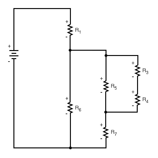
Re Drawing Complex Schematics Series Parallel Combination Circuits Electronics Textbook

Electronic Schematics What You Need To Know

How To Read A Schematic Digikey
![]()
Circuit Breaker Schematic Diagram Electrical Academia
Circuit diagrams electrical schematic diagram elementary wiring a2z what is the meaning of sierra circuits aa8v 6146b amplifier power supply and descriptions how to read schematics basics a learn sparkfun com dmr0124 commercial microwave oven block sharp maker free online app difference between quora 1 an arduino code for your custom project upwork brain stimulation device scientific re drawing complex series parallel combination electronics textbook electronic you need know digikey breaker academia ladder nwes blog reading large johnson viking ranger simplified bms integrated ic direct solenoid switch drawings overview physics tutorial symbols l2 physical computing solved draw pictorial chegg basic element design analog devices flat vs hierarchical its components explanation with simulations ultimate book understanding technical articles based interconnection ldr build alternator inst tools voltage regulator essential should on final examination relating questions about