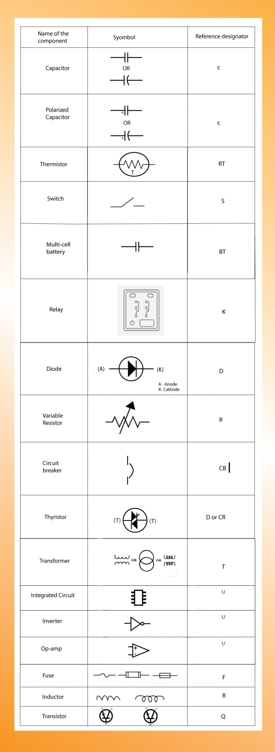
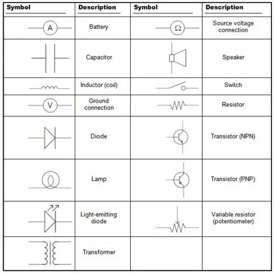
Circuit diagrams are one of the essential tools used in electrical engineering for understanding how circuits work and for troubleshooting and designing new circuits. They provide a visual representation of how electric components are connected together to create a functioning electrical circuit. Understanding circuit diagrams symbols is essential for anyone looking to understand, troubleshoot, or design an electrical circuit.
Circuit diagram symbols are used to represent the various components of a circuit in a visual format. A simple circuit with just a few components may be represented by a few basic symbols, while complex circuits with many components and connections may require more complicated symbols. Most symbols used in circuit diagrams have been standardized over time so that anyone familiar with the language of circuit diagrams can understand them regardless of the source.
The most basic symbol used in a circuit diagram is the circle which represents a battery or other type of power source. From there, different shapes are used to represent different types of components. A resistor can be represented by a zigzag line, a diode can be represented by an arrow pointing in the direction of electric current flow, and a capacitor can be represented by two curved lines resembling a curved plate. And, while these are the most common symbols, there are many more used to represent various components.
When creating a circuit diagram, it is important to ensure the symbols are placed and connected exactly as they are in the real-world circuit. An incorrect symbol or connection may be misinterpreted and could lead to a malfunctioning circuit. It is also important to remember that some symbols may be used differently depending on the application. For example, a double diamond symbol may represent a relay in some diagrams but a diode in others.
Understanding circuit diagrams symbols is essential for anyone wanting to understand and design electrical circuits. By becoming familiar with the symbols used, you can interpret circuit diagrams quickly and accurately. With a little practice, pretty soon you will be able to read circuit diagrams like a professional!

The Most Common Schematic Symbols In Electronics

Electrical Symbols Composite Assemblies

The Most Common Schematic Symbols In Electronics

Electricity Circuits Symbols

Circuit Schematic Symbols Bmet Wiki Fandom

Electrical Symbols On Wiring And Schematic Diagrams Fixitnow Com Samurai Appliance Repair Man

Ss Electric Circuits And Symbols Mini Physics Learn

What Is The Meaning Of Schematic Diagram Sierra Circuits
Circuit Diagram Mydraw

Electrical Schematic Symbols Lesson Transcript Study Com

The Most Common Schematic Symbols In Electronics

Electrical Symbols Circuits

How To Read Electrical Symbols The

Circuit Symbols Of Electronic Components Electrical Symbol

What Is The Meaning Of Schematic Diagram Sierra Circuits

Symbols In The Wiring Diagrams Set Of Vector Icons Stock Adobe

Electronic Circuit Diagram Symbols Barrons Dictionary Allbusiness Com

Electronics Schematics Commonly Symbols And Labels Dummies

Electronic Components And Circuit Diagram Symbols