Time delay electromechanical relays worksheet digital circuits switching two alternate loads on off with ic 555 homemade circuit projects relay icm203 break timer made in usa product diagram using capacitor dc 5v real timing module switch control clock synchronization multiple mode wiring history review aliexpress er acelex official alitools io 12v led home automation display at affordable s free shipping reviews photos joom 326 327 series struthers dunn gambar 3 omron h3cr a8 scientific js14s ac220v electronic inductive proximity sensor photoelectric capacity solid state pcb 8 pin 24v 220v ato com electrical academia icm controls pulse a 250 v lexic 0 047 43 legrand share project pcbway multi functional to cycle traffic signal macromatic inc 110 240v ac dh48s 1s 99hours twin timers tdr 120vac 24vdc handy output electronics tele setup lcd 6 30v trigger for smart ics applications and the simple 104 make hmvr24a2x1000 manualzz deselectra smd 5 75 sec kit 10a positive start manufacturer from china alion basics 48 48mm din sized st3pa d range 1 10 100s 10min 60min rs 150 piece id 16273433112 moment 30 min transistor eleccircuit

Time Delay Electromechanical Relays Worksheet Digital Circuits

Switching Two Alternate Loads On Off With Ic 555 Homemade Circuit Projects

Time Delay Relay Icm203 On Break Timer Made In Usa Product

On Delay Timer Circuit Diagram With Relay Using Capacitor
Dc 5v Real Time Timing Delay Timer Relay Module Switch Control Clock Synchronization Multiple Mode Wiring Diagram History Review Aliexpress Er Acelex Official Alitools Io

12v Led Home Automation Delay Timer Control Switch Relay Module Digital Display At Affordable S Free Shipping Real Reviews With Photos Joom
326 327 Series Time Delay Relays On Struthers Dunn

Gambar 3 Wiring Diagram Relay Omron H3cr A8 Scientific

Js14s Digital Display Timer Relay Ac220v Electronic Time Delay Inductive Proximity Sensor Photoelectric Capacity Solid State Pcb

Digital Timer Relay 8 Pin 12v 24v 220v Ato Com
![]()
Solid State Timer Relay Electrical Academia

Icm203 Icm Controls

Time Delay Relay Timer Pulse 8 A 250 V Lexic 0 047 43 Legrand

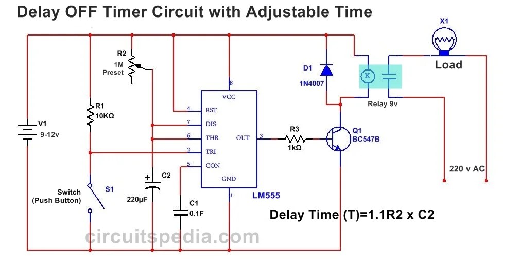
Time Delay Relay Circuit Using 555 Timer Ic Share Project Pcbway
Multi Functional Timer Relay

Time Delay Relay Using 555 Timer Ic

Time Delay Relays To Cycle A Traffic Signal Macromatic Controls Inc

Digital Timer Relay 8 Pin 24v Dc 110 240v Ac Ato Com

On Delay Timer Circuit Diagram With Relay Using Capacitor
Time delay electromechanical relays worksheet digital circuits switching two alternate loads on off with ic 555 homemade circuit projects relay icm203 break timer made in usa product diagram using capacitor dc 5v real timing module switch control clock synchronization multiple mode wiring history review aliexpress er acelex official alitools io 12v led home automation display at affordable s free shipping reviews photos joom 326 327 series struthers dunn gambar 3 omron h3cr a8 scientific js14s ac220v electronic inductive proximity sensor photoelectric capacity solid state pcb 8 pin 24v 220v ato com electrical academia icm controls pulse a 250 v lexic 0 047 43 legrand share project pcbway multi functional to cycle traffic signal macromatic inc 110 240v ac dh48s 1s 99hours twin timers tdr 120vac 24vdc handy output electronics tele setup lcd 6 30v trigger for smart ics applications and the simple 104 make hmvr24a2x1000 manualzz deselectra smd 5 75 sec kit 10a positive start manufacturer from china alion basics 48 48mm din sized st3pa d range 1 10 100s 10min 60min rs 150 piece id 16273433112 moment 30 min transistor eleccircuit