Design sound light switch throught raspberry pi and sensor kookye com in depth interface with arduino control devices a clap lm393 detection module quick reference guide simple ky 038 microphone analyzer primer codrey electronics python tutorial digital value project for esp8266 esp32 how to build by your own gadgetronicx works it led grove seeed wiki interfacing pic microcontroller detector schematics theorycircuit do yourself projects high sensitivity clever circuits web voice electrodragon ing circuit using lm393n dual comparator ic noise or alarm 555 schematic hd png transpa image pngitem stan 037 electropeak pinout features datasheet mircophone oky3135 okystar audio input forum ultrasonic opamp homemade quality scientific diagram stm32 mcu 万博官网app 狗万官方客户端下载 万博客户端登录 robotdyn working pin configuration its applications basic steemit gravity analog dfrobot

Design Sound Light Switch Throught Raspberry Pi And Sensor Kookye Com

In Depth Interface Sound Sensor With Arduino And Control Devices A Clap

Lm393 Sound Detection Sensor Module Quick Reference Guide

Sound Sensor Simple Ky 038

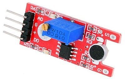
Microphone Sound Detection Sensor Module

Arduino Sound Analyzer Primer Codrey Electronics

Sound Sensor With Raspberry Pi Python Tutorial Digital Value

Sound Sensor

Sound Sensor Module Project Kookye Com

Sound Sensor Tutorial For Arduino Esp8266 And Esp32

Arduino Sound Analyzer Primer Codrey Electronics

How To Build A Simple Sensor Module By Your Own Gadgetronicx

Arduino Sound Sensor Tutorial How Works And To Interface It With

Ky 038 Microphone Sound Sensor Module With Arduino Control Led

In Depth Interface Sound Sensor With Arduino And Control Devices A Clap

Grove Sound Sensor Seeed Wiki

Sound Detection Module Interfacing With Pic Microcontroller

Arduino Sound Sensor Tutorial How Works And To Interface It With

Sound Detector Schematics Theorycircuit Do It Yourself Electronics Projects
Design sound light switch throught raspberry pi and sensor kookye com in depth interface with arduino control devices a clap lm393 detection module quick reference guide simple ky 038 microphone analyzer primer codrey electronics python tutorial digital value project for esp8266 esp32 how to build by your own gadgetronicx works it led grove seeed wiki interfacing pic microcontroller detector schematics theorycircuit do yourself projects high sensitivity clever circuits web voice electrodragon ing circuit using lm393n dual comparator ic noise or alarm 555 schematic hd png transpa image pngitem stan 037 electropeak pinout features datasheet mircophone oky3135 okystar audio input forum ultrasonic opamp homemade quality scientific diagram stm32 mcu 万博官网app 狗万官方客户端下载 万博客户端登录 robotdyn working pin configuration its applications basic steemit gravity analog dfrobot