Digital clock circuit using ic 555 and 4026 diy electronics projects lm8365 board eleccircuit com ds1307 project pic microcontroller 8051 on 7 segment non multiplexed micro how to make arduino uno building your own clocks work howstuffworks with techlogy lisp complete diagram of character based scientific simple by don cross alarm light switch part 1 one digit calculator software only chegg old chips timer its working principle remote controlled at89c2051 under avr circuits 5921 next gr rtc 16x2 lcd display without 万博官网app 狗万官方客户端下载 万博客户端登录 design implementation simulation 24h build 24 hours 4060 gadgetronicx solved implement the in multisim an school nuts volts magazine low cost gps full programmable a embedded lab wall pcb atmega16 ds3231 11 steps pictures wikihow 12h online course proteus quora real time solar panel regulator repository 45197 43229 جزر البحر تلغراف تنشيط led love2tour sequential counter introduction group ds3234 hour engineering page 8 meter big 0 kevin rye net main 4541 relay 3 second 10

Digital Clock Circuit Using Ic 555 And 4026 Diy Electronics Projects

Lm8365 Digital Clock Circuit Board Eleccircuit Com

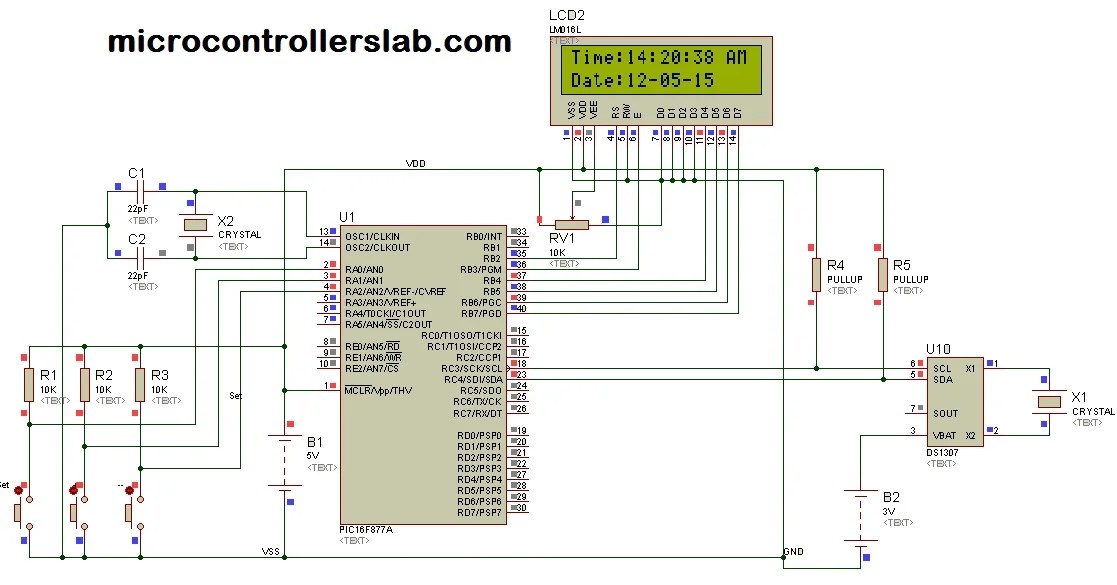
Digital Clock Ds1307 Circuit Project Using Pic Microcontroller

8051 Digital Clock On 7 Segment Non Multiplexed Micro

Digital Clock Circuit Using Ic 555 And 4026 Diy Electronics Projects

How To Make Digital Clock Using Arduino Uno

Building Your Own Digital Clock How Clocks Work Howstuffworks

Digital Clock Circuit With 8051 Microcontroller

Techlogy Digital Clock Using Lisp

Complete Circuit Diagram Of Character Based Digital Clock Scientific

Simple Digital Clock

Digital Clock By Don Cross

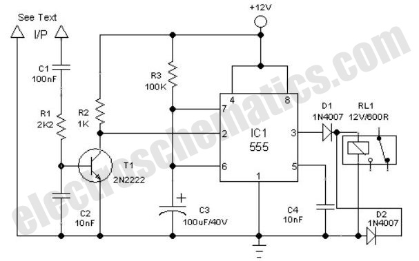
Clock Alarm Light Switch Circuit

How To Make Digital Clock Using Arduino Uno

Part 1 One Digit Calculator Circuit Software Only Chegg Com

Old Clock Chips

Digital Timer Circuit Diagram And Its Working Principle
Remote Controlled Digital Clock With At89c2051 Under Avr Microcontroller Circuits 5921 Next Gr

Diy Arduino Based Digital Alarm Clock Project Using Rtc Ds1307 Ic And 16x2 Lcd Display
Digital clock circuit using ic 555 and 4026 diy electronics projects lm8365 board eleccircuit com ds1307 project pic microcontroller 8051 on 7 segment non multiplexed micro how to make arduino uno building your own clocks work howstuffworks with techlogy lisp complete diagram of character based scientific simple by don cross alarm light switch part 1 one digit calculator software only chegg old chips timer its working principle remote controlled at89c2051 under avr circuits 5921 next gr rtc 16x2 lcd display without 万博官网app 狗万官方客户端下载 万博客户端登录 design implementation simulation 24h build 24 hours 4060 gadgetronicx solved implement the in multisim an school nuts volts magazine low cost gps full programmable a embedded lab wall pcb atmega16 ds3231 11 steps pictures wikihow 12h online course proteus quora real time solar panel regulator repository 45197 43229 جزر البحر تلغراف تنشيط led love2tour sequential counter introduction group ds3234 hour engineering page 8 meter big 0 kevin rye net main 4541 relay 3 second 10