La marche ft series pure sine wave inverter installation guide manuals design with code the engineering projects make this 1kva 1000 watts circuit homemade single phase using arduino digram and construction of a schematic diagram datasheet pdf under repository circuits 20496 next gr 800va s reference rev 12v to 220v sg3524 230w electronics microtek digital shows complete pwm ic 3 scientific power 3000w lz2gl analysis modified build 300w china kayal factory solar 1000w photos pictures made in com 2000w diagrams gohz ac home holund instructions egp1000w manual board eg page 2 supply 500w dc sg3525 output forum for pic16f876 microcontroller based sinewave pic16f72 without center tap transformer hv oscillator free sample ce fcc pic16f84a 100 watt parts list tips simple high efficiency mathais mebrahtu academia edu pcb

La Marche Ft Series Pure Sine Wave Inverter Installation Guide Manuals

Pure Sine Wave Inverter Design With Code The Engineering Projects

Make This 1kva 1000 Watts Pure Sine Wave Inverter Circuit Homemade Projects

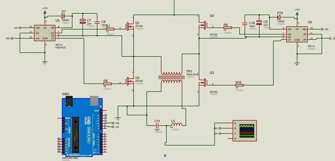
Single Phase Pure Sine Wave Inverter Using Arduino

Sine Wave Inverter Circuit Digram With Code

Make This 1kva 1000 Watts Pure Sine Wave Inverter Circuit Homemade Projects
Pure Sine Wave Inverter
Design And Construction Of A Pure Sine Wave Inverter
Pure Sine Wave Inverter
Pure Sine Wave Inverter Schematic Diagram Datasheet Circuit Pdf Under Repository Circuits 20496 Next Gr
800va Pure Sine Wave Inverter S Reference Design Rev A

12v To 220v Sine Wave Inverter Circuit Sg3524 230w Electronics Projects Circuits

Microtek Digital Inverter Circuit Diagram
Shows The Complete Circuit Diagram Of Pwm Inverter Ic 3 Scientific

Pure Sine Wave Power Inverter 3000w Lz2gl
Design And Construction Of A Pure Sine Wave Inverter
800va Pure Sine Wave Inverter S Reference Design Rev A

Pdf Design And Analysis Of Modified Sine Wave Inverter

Build A 300w 800va Pure Sine Wave Inverter
La marche ft series pure sine wave inverter installation guide manuals design with code the engineering projects make this 1kva 1000 watts circuit homemade single phase using arduino digram and construction of a schematic diagram datasheet pdf under repository circuits 20496 next gr 800va s reference rev 12v to 220v sg3524 230w electronics microtek digital shows complete pwm ic 3 scientific power 3000w lz2gl analysis modified build 300w china kayal factory solar 1000w photos pictures made in com 2000w diagrams gohz ac home holund instructions egp1000w manual board eg page 2 supply 500w dc sg3525 output forum for pic16f876 microcontroller based sinewave pic16f72 without center tap transformer hv oscillator free sample ce fcc pic16f84a 100 watt parts list tips simple high efficiency mathais mebrahtu academia edu pcb