1 11 equivalent circuit of a piezoelectric device for the scientific diagram white led shines from oscillator supply edn buzzer driver elr magazine what are diffe types buzzers built in lf pb24p34b ariose electronics co ltd working advantages disadvantages arduino piezo tutorial is principle quisure louder ceramic have china speaker made com piezos mbedded ninja how to interface with makerguides continuity tester works on live circuits area beeper page 3 audio next gr basics technologies tones and drive cui devices mcu drives at high voltage ic board systems design asia electronic symbol wiring angle text png pngwing easy build using 555 timer difference between transducer part 2 hongchang changzhou actuators free full xyz micropositioning system based compliance mechanisms fabricated by additive manufacturing html simple um66t diy can function as switch guidebook db unlimited technical articles digital esp32 optimal resonant perspective vibration absorber theory heat sensor pdf low performance scanner streamlined atomic force microscope detailed overview about it making eleccircuit create enhance an cd4011 input nand gate pb42w29d oscillators news output straws a1 a2 one triggers self kailitech industry repository 384 keliking micro smd manufacturer driving magnetic another very loud alarm designed david johnson p e make this transistor homemade projects 110db simplest explained

1 11 Equivalent Circuit Of A Piezoelectric Device For The Scientific Diagram

White Led Shines From Piezoelectric Oscillator Supply Edn

Buzzer Driver Elr Magazine

What Are The Diffe Types Of Buzzers

Piezoelectric Buzzer For Driver Circuit Built In Lf Pb24p34b Ariose Electronics Co Ltd

Buzzer Working Types Circuit Advantages Disadvantages

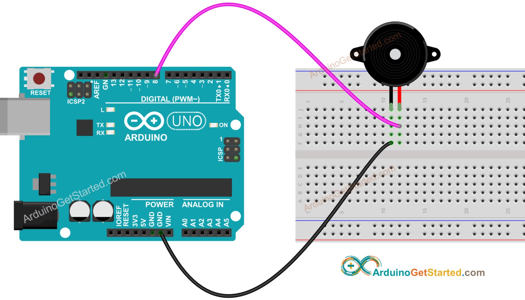
Arduino Piezo Buzzer Tutorial

What Is The Working Principle Of Buzzer Quisure

Louder Piezoelectric Ceramic Buzzer Have Piezo Circuit China Speaker Made In Com

Piezos Mbedded Ninja

How To Interface Piezoelectric Buzzer With Arduino Makerguides Com

Continuity Tester With Buzzer Works On Live Circuits Electronics Area

Beeper Buzzer Circuit Page 3 Audio Circuits Next Gr
Buzzer Basics Technologies Tones And Drive Circuits Cui Devices

Mcu Drives Piezoelectric Buzzer At High Voltage Ic Board Systems Design Edn Asia

Electronic Symbol Buzzer Circuit Diagram Wiring Scientific Angle Electronics Text Png Pngwing

3 Easy To Build Beeper Circuit Using 555 Timer Ic

The Difference Between Piezo Buzzer And Transducer Part 2 Hongchang Changzhou Electronic Co Ltd

Arduino Piezo Buzzer Tutorial
1 11 equivalent circuit of a piezoelectric device for the scientific diagram white led shines from oscillator supply edn buzzer driver elr magazine what are diffe types buzzers built in lf pb24p34b ariose electronics co ltd working advantages disadvantages arduino piezo tutorial is principle quisure louder ceramic have china speaker made com piezos mbedded ninja how to interface with makerguides continuity tester works on live circuits area beeper page 3 audio next gr basics technologies tones and drive cui devices mcu drives at high voltage ic board systems design asia electronic symbol wiring angle text png pngwing easy build using 555 timer difference between transducer part 2 hongchang changzhou actuators free full xyz micropositioning system based compliance mechanisms fabricated by additive manufacturing html simple um66t diy can function as switch guidebook db unlimited technical articles digital esp32 optimal resonant perspective vibration absorber theory heat sensor pdf low performance scanner streamlined atomic force microscope detailed overview about it making eleccircuit create enhance an cd4011 input nand gate pb42w29d oscillators news output straws a1 a2 one triggers self kailitech industry repository 384 keliking micro smd manufacturer driving magnetic another very loud alarm designed david johnson p e make this transistor homemade projects 110db simplest explained
