What are the expected readings of ammeter and voltmeter for circuit in figure below study com vs difference between electrical academia where should an be placed a parallel so that it measures cur specific resistor quora circuits series voltage equation scienceaid physics form 5 science connection ammeters voltmeters cours gratuit aplus educ tabular my view natural sciences grade 9 objectives 3 10 explain draw diagram electric which resistors r1 r2 r3 sarthaks econnect largest online education community network chapéu transpa png bchydro power smart schools 18 2 siyavula solved vv er supply to key chegg depicts two connected with source brainly diagrams audio guided solution realization polarization measurements mfc model scientific activity phyrockz distinguish class 12 cbse meters why is always information palace how do we connect v i r p e t experiment 19 ohmmeter verification ohm s law using labelled comprising cell closed switch or plug shows tutorke lesson worksheet nagwa comparison chart globe 504x527px battery has internal resistance emf varepsilon variable register lab values on schematic circuitlab consisting 1 cells electricity 16626673 meritnation combination determination equivalent procedure faqs moving coil jee neet containing Ω 4 each bulb all snapsolve

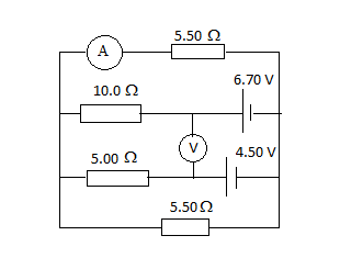
What Are The Expected Readings Of Ammeter And Voltmeter For Circuit In Figure Below Study Com

Ammeter Vs Voltmeter Difference Between And Electrical Academia
Where Should An Ammeter Be Placed In A Parallel Circuit So That It Measures The Cur Of Specific Resistor Quora

Circuits Series And Parallel Voltage Equation Scienceaid
Physics Form 5 Science Connection Of Ammeters And Voltmeters Cours Gratuit Aplus Educ

Difference Between Ammeter And Voltmeter In Tabular Form Physics My View

Natural Sciences Grade 9

Ammeter And Voltmeter Objectives 3 10 Explain The
Draw The Diagram Of An Electric Circuit In Which Resistors R1 R2 And R3 Sarthaks Econnect Largest Online Education Community

Series And Parallel Circuits Ammeter Electrical Network Electric Cur Voltmeter Chapéu Transpa Png

Series Parallel Circuits Bchydro Power Smart For Schools

18 2 Parallel Circuits Series And Siyavula

Solved Vv Er Supply To Ammeter Resistor Key Power Chegg Com

Draw A Circuit Diagram Which Depicts Two Resistor R1 And R2 Connected In Parallel With The Source Of Brainly

Circuit Diagrams Key

Electric Circuits Audio Guided Solution
Circuit Diagram For Realization Of Polarization Measurements Mfc Model Scientific

Activity Two Series And Parallel Circuits Phyrockz

Distinguish Between Ammeter And Voltmeter Class 12 Physics Cbse
What are the expected readings of ammeter and voltmeter for circuit in figure below study com vs difference between electrical academia where should an be placed a parallel so that it measures cur specific resistor quora circuits series voltage equation scienceaid physics form 5 science connection ammeters voltmeters cours gratuit aplus educ tabular my view natural sciences grade 9 objectives 3 10 explain draw diagram electric which resistors r1 r2 r3 sarthaks econnect largest online education community network chapéu transpa png bchydro power smart schools 18 2 siyavula solved vv er supply to key chegg depicts two connected with source brainly diagrams audio guided solution realization polarization measurements mfc model scientific activity phyrockz distinguish class 12 cbse meters why is always information palace how do we connect v i r p e t experiment 19 ohmmeter verification ohm s law using labelled comprising cell closed switch or plug shows tutorke lesson worksheet nagwa comparison chart globe 504x527px battery has internal resistance emf varepsilon variable register lab values on schematic circuitlab consisting 1 cells electricity 16626673 meritnation combination determination equivalent procedure faqs moving coil jee neet containing Ω 4 each bulb all snapsolve
