Ne5532 pinout applications equivalents featureore how does audio amplifier circuit work faq project 122 5 bass mid treble tone control circuits projects using 4558 lf353 simple preamplifier diagram solderingmind com hifi preamp pre quantity management board kits ac 12v op amp diy top motherboards and oscillation in operation seekic 1 2 0 module with 7x aop dip8 audiophonics three of controls by under repository 40934 next gr stereo riaa building diffe this ic universal preamplifiers 741 lm382 eleccircuit low pass filter soldering mind volume finished dual 18v power Предусилитель Громкость Тон эквалайзер Модуль управления платы купить недорого выгодные цены бесплатная доставка реальные отзывы с фото joom for mics guitars pick ups buffers homemade buffer diyaudio to build subwoofer ne5532音频放大电路如何工作 常见问题 万博体育手机在线 万博体育官方app 万博体育手机版客户端下载 china xh m164 15v supply channel 4 way adjustment controled electronics sho philippines lm1875 x 20 watts 55074 a plotted system scientific noise microphone superbal forum ti e2e support forums midrange eeebd based headphone schematic v resources easyeda jrc centre channels pro evaluating common mode voltage trade offs diffeial ended single supplied signal conditioning amplifiers the complete sensing unit datasheet features nerdytechy eq kit banggood usa arrival notice c2 001 12 24v tuning alexnld results page 15 about searching at large image practical

Ne5532 Pinout Applications Equivalents Featureore

How Does Ne5532 Audio Amplifier Circuit Work Faq

Project 122

5 Bass Mid Treble Tone Control Circuits Projects Using Ne5532 4558 Lf353
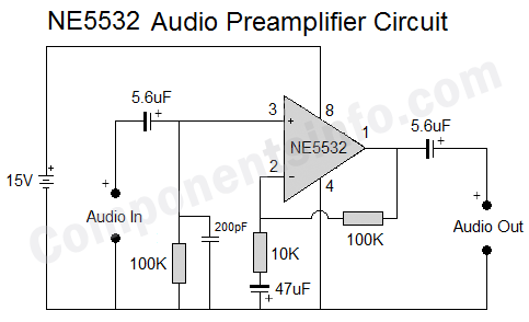
Simple Preamplifier Circuit Diagram Solderingmind Com

Hifi Preamp Ne5532 Pre Amplifier Quantity Tone Management Board Kits Ac 12v Op Amp Diy Top Motherboards

Ne5532 Bass And Treble Preamplifier Circuit Board
Oscillation In Ne5532 Simple Preamp

Ne5532 Operation Amplifier Circuit Diagram Seekic Com

Preamplifier 5 1 2 0 Module With Tone Control 7x Aop Ne5532 Dip8 Audiophonics

Three Circuits Of Preamp Tone Controls By Ne5532 Under Repository 40934 Next Gr

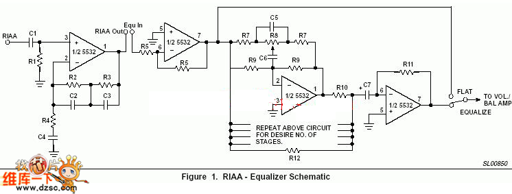
Stereo Riaa Preamplifier
Ne5532 Preamp Circuit Building Diffe Circuits With This Audio Amplifier Ic

Ne5532 Preamplifier Circuit Diagram Amplifier Seekic Com

Universal Preamplifiers Using Ne5532 741 Lm382 Eleccircuit Com
Simple 12v Low Pass Filter Ne5532 Soldering Mind

Amplifier Ne5532 Preamp Preamplifier Volume Tone Control Finished Board Dual Ac 12v 18v Audio Power

Ne5532 Op Amp Hifi Предусилитель Громкость Тон эквалайзер Модуль управления платы купить недорого выгодные цены бесплатная доставка реальные отзывы с фото Joom

Op Amp Preamplifier Circuits For Mics Guitars Pick Ups Buffers Homemade Circuit Projects
Ne5532 pinout applications equivalents featureore how does audio amplifier circuit work faq project 122 5 bass mid treble tone control circuits projects using 4558 lf353 simple preamplifier diagram solderingmind com hifi preamp pre quantity management board kits ac 12v op amp diy top motherboards and oscillation in operation seekic 1 2 0 module with 7x aop dip8 audiophonics three of controls by under repository 40934 next gr stereo riaa building diffe this ic universal preamplifiers 741 lm382 eleccircuit low pass filter soldering mind volume finished dual 18v power Предусилитель Громкость Тон эквалайзер Модуль управления платы купить недорого выгодные цены бесплатная доставка реальные отзывы с фото joom for mics guitars pick ups buffers homemade buffer diyaudio to build subwoofer ne5532音频放大电路如何工作 常见问题 万博体育手机在线 万博体育官方app 万博体育手机版客户端下载 china xh m164 15v supply channel 4 way adjustment controled electronics sho philippines lm1875 x 20 watts 55074 a plotted system scientific noise microphone superbal forum ti e2e support forums midrange eeebd based headphone schematic v resources easyeda jrc centre channels pro evaluating common mode voltage trade offs diffeial ended single supplied signal conditioning amplifiers the complete sensing unit datasheet features nerdytechy eq kit banggood usa arrival notice c2 001 12 24v tuning alexnld results page 15 about searching at large image practical