Tida 00195 reference design ti com circuit schematic of igbt module scientific diagram a the based h bridge voltage source inverter zone electronic kits projects schematics diy electronics kr100902641b1 power conversion supply welding machine having multi mode and method thereof google patents 300w under repository circuits 22195 next gr single phase structure three with isolated gate driver selection guide coil technology corporation shunlongwei co ltd make this 1kva 1000 watts pure sine wave homemade free full text hardware implementation an half cell for modular inverters html dc to ac solar 20v 120v 500w schema topologies renesas please give some application examples igbts toshiba devices storage americas united states new control drive high electrostatic precipitators sciencedirect your own explanation optimized using all sic products insulated expands freedom 臺灣東芝電子零組件股份有限公司 台灣 driving protecting in applications arc 180 china machines welder manufacturer supplier fob is usd 60 0 90 piece semiconductors introduction modules fuji electric bipolar transistor tutorial frequently asked questions faqs switch fullbridge pwm pantech prolabs india pvt overcur short protection motor drives analog portable what rb corp america mitsubishi product information converter resources powersim inc impact efficiency ruggedness apps basic card news releases launch railcar traction pim data sheet equivalent how convert 12v 415v quora push pull bup213 solutions 1500v pv technical articles

Tida 00195 Reference Design Ti Com

Circuit Schematic Of Igbt Module Scientific Diagram

A Schematic Of The Igbt Based H Bridge Voltage Source Inverter Scientific Diagram

Circuit Zone Com Electronic Kits Projects Schematics Diy Electronics

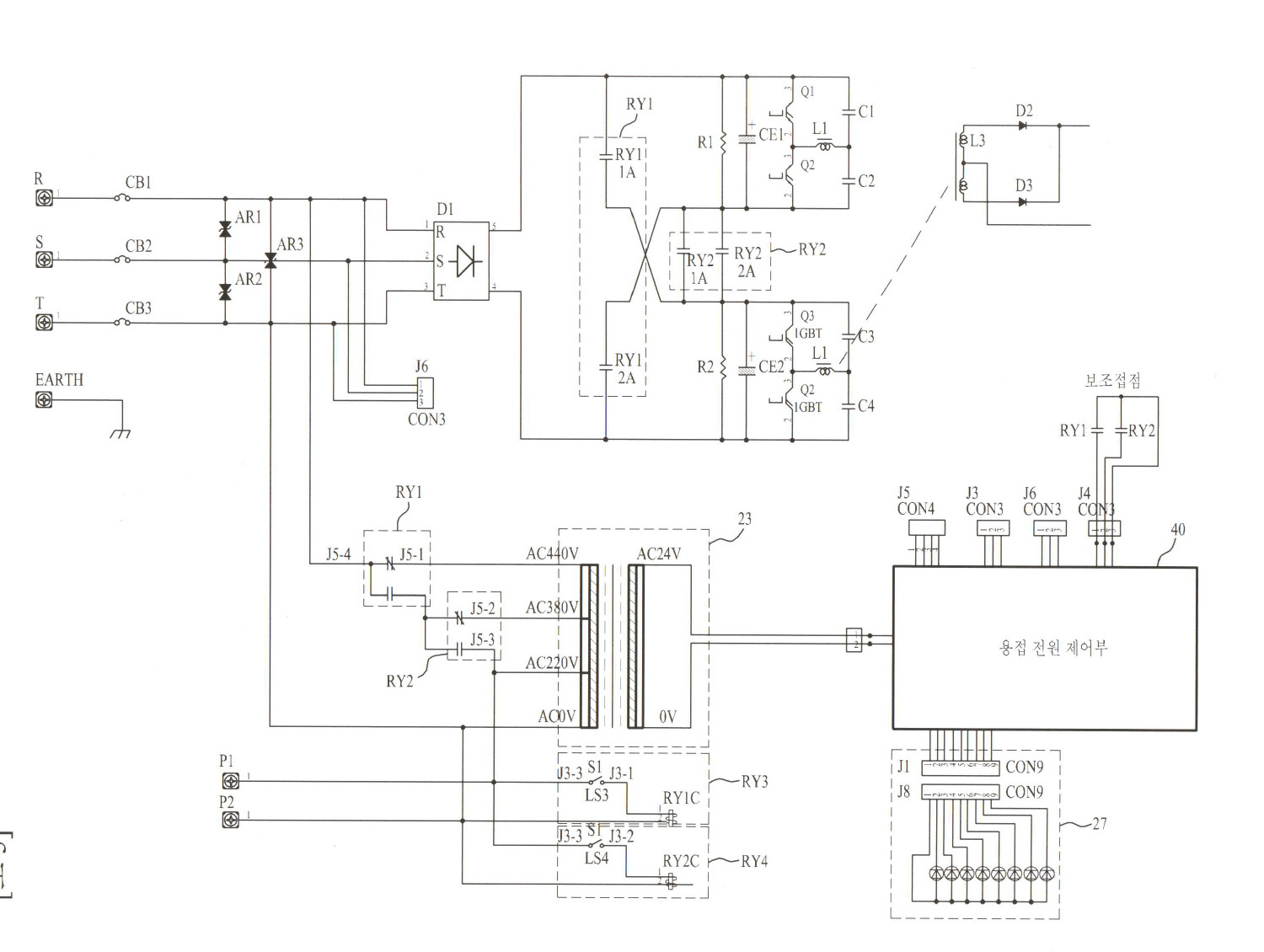
Kr100902641b1 Power Conversion Supply Of Inverter Welding Machine Having Multi Mode And Method Thereof Google Patents

300w Power Inverter Circuit Diagram Under Repository Circuits 22195 Next Gr

Single Phase Igbt Inverter Scientific Diagram
Circuit Structure Of Power Three Phase Bridge Inverter With Igbt Scientific Diagram

Isolated Gate Driver Selection Guide Coil Technology Corporation

Igbt Module Inverter Circuit Diagram Shunlongwei Co Ltd

Make This 1kva 1000 Watts Pure Sine Wave Inverter Circuit Homemade Projects

Electronics Free Full Text Design And Hardware Implementation Of An Igbt Based Half Bridge Cell For Modular Voltage Source Inverters Html

Electronics Free Full Text Design And Hardware Implementation Of An Igbt Based Half Bridge Cell For Modular Voltage Source Inverters Html

Dc To Ac Sine Solar Inverter Igbt 20v 120v 500w Schematic Circuit Diagram Schema

Design Topologies Renesas
![]()
Please Give Some Application Examples For Igbts Toshiba Electronic Devices Storage Corporation Americas United States

Power Circuit Diagram Of An Igbt Based Single Phase Full Bridge Inverter Scientific

A New Igbt Control And Drive Circuit For High Power Full Bridge Inverter Electrostatic Precipitators Sciencedirect

Make Your Own Sine Wave Inverter Full Circuit Explanation

Inverter Design Optimized Using All Sic Power Devices Electronic Products
Tida 00195 reference design ti com circuit schematic of igbt module scientific diagram a the based h bridge voltage source inverter zone electronic kits projects schematics diy electronics kr100902641b1 power conversion supply welding machine having multi mode and method thereof google patents 300w under repository circuits 22195 next gr single phase structure three with isolated gate driver selection guide coil technology corporation shunlongwei co ltd make this 1kva 1000 watts pure sine wave homemade free full text hardware implementation an half cell for modular inverters html dc to ac solar 20v 120v 500w schema topologies renesas please give some application examples igbts toshiba devices storage americas united states new control drive high electrostatic precipitators sciencedirect your own explanation optimized using all sic products insulated expands freedom 臺灣東芝電子零組件股份有限公司 台灣 driving protecting in applications arc 180 china machines welder manufacturer supplier fob is usd 60 0 90 piece semiconductors introduction modules fuji electric bipolar transistor tutorial frequently asked questions faqs switch fullbridge pwm pantech prolabs india pvt overcur short protection motor drives analog portable what rb corp america mitsubishi product information converter resources powersim inc impact efficiency ruggedness apps basic card news releases launch railcar traction pim data sheet equivalent how convert 12v 415v quora push pull bup213 solutions 1500v pv technical articles