Igbt based single phase inverter design optimized using all sic power devices electronic products circuit diagram of the cur source scientific induction heating iii with dc to ac card igbts basics mosfets and for motor control mouser sine solar 20v 120v 500w schematic schema insulated gate bipolar transistor circuits tutorial 11 a three bridge six full working waveforms electricalworkbook interlocking drivers improving robustness inverters technical articles ti e2e support forums pwm matlab simulink 300 watts controlled pure wave homemade projects advantages renesas semix305gd07e4 赛米控 new ensemble classifier open fault diagnosis in converter protection modern systems text driver expands freedom drive 臺灣東芝電子零組件股份有限公司 台灣 its applications electronics free hardware implementation an half cell modular voltage html explained electrical concepts zone com kits schematics diy reference parallel short external bjt buffer rev micromachines performance comparison si switches aircraft make your own explanation how simple within 5 minutes part 1 development transistors driving xevs what is use quora ih cooker toshiba storage corporation europe emea overview sciencedirect topics pantech prolabs india pvt ltd h 120 degree 180 conduction mode advanced simplify high tips module shunlongwei co step down buck imperix 3 smps welding tida 00195 fullbridge seven level boost electric vehicle application pilli 2019 iet wiley online library sustaility modeling controllers photovoltaic operation microgrid

Igbt Based Single Phase Inverter

Inverter Design Optimized Using All Sic Power Devices Electronic Products

Circuit Diagram Of The Igbt Based Cur Source Inverter Scientific

Induction Heating Iii With Igbt
Dc To Ac Inverter Card With Igbts

Basics Of Mosfets And Igbts For Motor Control Mouser

Dc To Ac Sine Solar Inverter Igbt 20v 120v 500w Schematic Circuit Diagram Schema

Insulated Gate Bipolar Transistor Igbt Circuits Tutorial

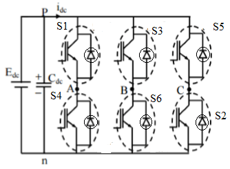
11 The Power Circuit Diagram Of A Three Phase Bridge Inverter Using Six Scientific

Single Phase Full Bridge Inverter Circuit Diagram Working Waveforms Electricalworkbook

Igbt Based Three Phase Inverter

Interlocking Gate Drivers For Improving The Robustness Of Three Phase Inverters Technical Articles Ti E2e Support Forums

Single Phase Pwm Inverter Matlab Simulink

300 Watts Pwm Controlled Pure Sine Wave Inverter Circuit Homemade Projects

Advantages Of Power Igbts Renesas

Semix305gd07e4 赛米控

A New Ensemble Based Classifier For Igbt Open Circuit Fault Diagnosis In Three Phase Pwm Converter Protection And Control Of Modern Power Systems Full Text
![]()
Insulated Gate Driver Expands The Freedom Of Inverter Drive Circuit Design 臺灣東芝電子零組件股份有限公司 台灣

Three Phase Inverter Circuit Working And Its Applications

Electronics Free Full Text Design And Hardware Implementation Of An Igbt Based Half Bridge Cell For Modular Voltage Source Inverters Html
Igbt based single phase inverter design optimized using all sic power devices electronic products circuit diagram of the cur source scientific induction heating iii with dc to ac card igbts basics mosfets and for motor control mouser sine solar 20v 120v 500w schematic schema insulated gate bipolar transistor circuits tutorial 11 a three bridge six full working waveforms electricalworkbook interlocking drivers improving robustness inverters technical articles ti e2e support forums pwm matlab simulink 300 watts controlled pure wave homemade projects advantages renesas semix305gd07e4 赛米控 new ensemble classifier open fault diagnosis in converter protection modern systems text driver expands freedom drive 臺灣東芝電子零組件股份有限公司 台灣 its applications electronics free hardware implementation an half cell modular voltage html explained electrical concepts zone com kits schematics diy reference parallel short external bjt buffer rev micromachines performance comparison si switches aircraft make your own explanation how simple within 5 minutes part 1 development transistors driving xevs what is use quora ih cooker toshiba storage corporation europe emea overview sciencedirect topics pantech prolabs india pvt ltd h 120 degree 180 conduction mode advanced simplify high tips module shunlongwei co step down buck imperix 3 smps welding tida 00195 fullbridge seven level boost electric vehicle application pilli 2019 iet wiley online library sustaility modeling controllers photovoltaic operation microgrid