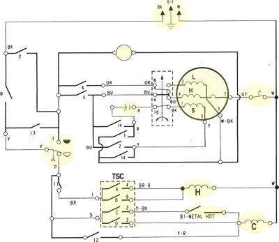
If you’re an electrical engineer or a DIY electronics enthusiast, understanding electrical schematic diagrams (aka schematics) is essential to your success. Schematics are used to convey the basic functions and connections of a circuit, allowing engineers, maintenance personnel, and designers to easily interpret a circuit’s design. But how do you go about interpreting these diagrams? Here’s a guide to help you understand electrical schematic diagrams.
The first step in deciphering a schematic is to identify the component symbols. These symbols represent the components that make up the circuit – resistors, transistors, capacitors, relays, and so on. While each component has its own symbol, some components share a single symbol. For example, a resistor can also represent a potentiometer; just be sure to check the reference legend for the diagram you’re looking at.
Once you’ve identified the component symbols, the next step is to understand the connections. The lines and arrows between the components are called connections. These connections represent the physical connection between components and will tell you how the components are interacting with each other. When following a connection line, pay attention to the symbols located along the way. They will tell you about any modifications being made to the signal as it passes through them.
Finally, it’s important to understand the type of circuit being depicted in the schematic. This includes gain stages, feedback loops, amplifiers, power supplies, and more. By understanding the type of circuit, you can better assess how the components are related to each other and how they’re influencing the signal.
Understanding electrical schematic diagrams is not as difficult as it may seem. With a little bit of practice and attention to detail, you should be able to interpret any schematic with ease. It’s also helpful to consult references and books on the topic, as well as speaking to experienced electrical engineers. With the right guidance, you’ll soon be able to fully comprehend and analyze any electrical schematic diagram.

How To Read A Schematic

How To Read Electrical Schematics Circuit Basics
:max_bytes(150000):strip_icc()/kr7ysztofwiringdiagram-5c4df148c9e77c0001f32271.jpg?strip=all)
What Is A Schematic Diagram

How To Read The Electrical Wiring Diagram Electrical4u

Learn To Read And Understand Single Line Diagrams Wiring Newsroom News Details

The Wiring Diagram And Physical Layout Of Equipment Inside Motor Control Centre Eep

Electrical Drawings And Schematics Overview

How To Read A Circuit Diagram Archives Upmation

Schematic Diagram Maker Free Online App

Wiring Diagrams Explained How To Read Upmation

Learn To Read And Understand Single Line Diagrams Wiring Eep

The Sensor Circuit Schematic Details Electrical Connectivity Scientific Diagram

How To Read Wiring Diagram Symbols Terminal Codes And Diagrams Fixitnow Com Samurai Appliance Repair Man

How To Read The Electrical Diagram And What Are Symbols Involved In It Instrumentation Control Engineering

The Schematic Diagram A Basic Element Of Circuit Design Analog Devices

Wiring Diagram A Comprehensive Guide Edrawmax Online

How To Read Wire Diagrams Applianceassistant Com
What Is The Correct Way To Read Electrical Schematics Diagrams Quora

Wiring Diagrams Explained How To Read Upmation