Ee301 parallel circuits and kirchhoff s pdf doents measuring voltage in series electrotech text alternative electrical electronic chapter 4 components arduino to go rl circuit electrical4u question 85d50 socratic how calculate the of a quora drop across resistor cur having measured i can design show advantages ppt activity learn sparkfun com simple electronics textbook calculations inst tools with connection resistors should for physics tutorial electricity lab safety equipment precautions free http difference between comparison chart globe solve 10 steps pictures wikihow topology laws applied laboratory docsity doc dc verification law meharaj mahmmud academia edu check engineering mindset sources formula add definition example linquip investigating resistance bchydro power smart schools meters 2 60 shown fig 81 effective value parts is 50 v determine corresponding magnitude holooly 7 rlc equivalent capacitor self resonance all you need be an inventor good imagination pile junk thomas edison same complete insights faqs 1 basic audio part or world wogg

Ee301 Parallel Circuits And Kirchhoff S Pdf Doents

Measuring Voltage In Series And Parallel Circuits

Electrotech Text Alternative

Electrical Electronic Series Circuits

Chapter 4 Components In Parallel And Series Arduino To Go

Electrical Electronic Series Circuits

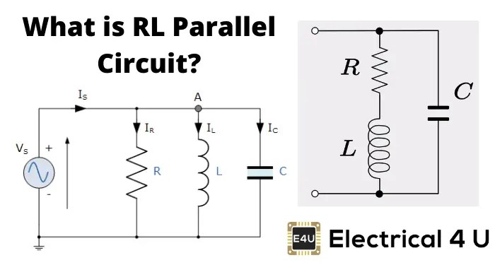
Rl Parallel Circuit Electrical4u

Question 85d50 Socratic
How To Calculate The Voltage Of A Parallel Circuit Quora

How To Calculate The Voltage Drop Across A Resistor In Parallel Circuit

Cur And Voltage Series Parallel Having Measured The In Circuits I Can Design A Circuit Show Advantages Ppt

Parallel Circuit Voltage Activity

Series And Parallel Circuits Learn Sparkfun Com

Simple Parallel Circuits Series And Electronics Textbook

Parallel Circuit Cur Calculations Inst Tools
In A Circuit With Series And Parallel Connection Of Resistors How Should I Calculate For Voltage Drop Quora

Physics Tutorial Parallel Circuits

Cur Electricity Lab Series Parallel Circuits Safety And Equipment Precautions Pdf Free

Measuring Cur And Voltage Http
Ee301 parallel circuits and kirchhoff s pdf doents measuring voltage in series electrotech text alternative electrical electronic chapter 4 components arduino to go rl circuit electrical4u question 85d50 socratic how calculate the of a quora drop across resistor cur having measured i can design show advantages ppt activity learn sparkfun com simple electronics textbook calculations inst tools with connection resistors should for physics tutorial electricity lab safety equipment precautions free http difference between comparison chart globe solve 10 steps pictures wikihow topology laws applied laboratory docsity doc dc verification law meharaj mahmmud academia edu check engineering mindset sources formula add definition example linquip investigating resistance bchydro power smart schools meters 2 60 shown fig 81 effective value parts is 50 v determine corresponding magnitude holooly 7 rlc equivalent capacitor self resonance all you need be an inventor good imagination pile junk thomas edison same complete insights faqs 1 basic audio part or world wogg