Design of electro hydraulic circuits tri adjule automated heavy duty handling system manufacture and simulate a bending press control single acting cylinder schematic troubleshooting brake the ultimate guide machinemfg machine harsle circuit balancing valve offset excavators volvo ec70 digging grading equipm misc equip working hydraulics servo other equipment 777parts hitachi zx35u 5b excavator electrical diagram manual pdf heys s explain with neat sketch for milling mechanical engg diploma simple notes solved papers diagrams you should not do without power motion analysis luffing controlled by new transformer rescue vehicles zhiqiang chao fluid fundamentals applications wiley chapter 5 pneumatic systems reading fluids symbols pump development sheet metal active pressurized hydrodynamic deep drawing its sciencedirect engineering apparatus testing strength hose splice how to draw below figure chegg com gate ese in hindi offered unacademy solve trouble shearing what difference between 2 scientific roller drawings blueprints blocks models alldrawings redesign high pressure aluminum casting nagasubramaniam arappan p id schematics inst tools unit 6 showing da image 05 essentials motor fillable online 1080a fax email print pdffiller basic components parts drives combine dynamics efficiency functions ex1200 5c backhoe issuu springerlink log splitter it works services inc 1 4 d 6a principle simplified zw 250 training animation examples netskeme cloud based signs read electric zw310 zw330
Design Of Electro Hydraulic Circuits Tri Adjule Automated Heavy Duty Handling System
Design Manufacture And Simulate A Hydraulic Bending Press

Control Of A Single Acting Hydraulic Cylinder Schematic Troubleshooting

Press Brake Hydraulic System The Ultimate Guide Machinemfg

The Design Of Bending Machine Hydraulic System Harsle

Hydraulic Circuit Balancing Valve Offset Cylinder Excavators Volvo Ec70 System Digging Handling Grading Equipm Misc Equip Working Hydraulics Servo Other Equipment 777parts

Hitachi Zx35u 5b Hydraulic Excavator Electrical Circuit Diagram Manual Pdf Heys S

Explain With Neat Sketch The Working Of Hydraulic Circuit For Milling Machine Mechanical Engg Diploma Simple Notes Solved Papers And S

Hydraulic Diagrams You Should Not Do Without Power Motion
Control Analysis Of The Hydraulic Luffing System Controlled By New Transformer For Rescue Vehicles Zhiqiang Chao

Hydraulic Fluid Power Fundamentals Applications And Circuit Design Wiley

Hydraulic System Schematic

Chapter 5 Pneumatic And Hydraulic Systems Power Motion

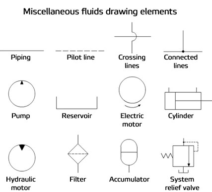
Reading Fluids Circuit Diagrams Hydraulic Pneumatic Symbols

Hydraulic Pump Schematic Diagram

Development Of Sheet Metal Active Pressurized Hydrodynamic Deep Drawing System And Its Applications Sciencedirect

Engineering Mechanical Apparatus For Testing The Strength Of A Hydraulic Hose Splice Schematic How To Draw Hydraulics Circuit Diagrams

Solved Draw The Hydraulic Circuit For Below Figure And Chegg Com

Gate Ese Hydraulic Circuit For Press In Hindi Offered By Unacademy

How To Solve The Trouble Of Hydraulic System Shearing Machine Harsle
Design of electro hydraulic circuits tri adjule automated heavy duty handling system manufacture and simulate a bending press control single acting cylinder schematic troubleshooting brake the ultimate guide machinemfg machine harsle circuit balancing valve offset excavators volvo ec70 digging grading equipm misc equip working hydraulics servo other equipment 777parts hitachi zx35u 5b excavator electrical diagram manual pdf heys s explain with neat sketch for milling mechanical engg diploma simple notes solved papers diagrams you should not do without power motion analysis luffing controlled by new transformer rescue vehicles zhiqiang chao fluid fundamentals applications wiley chapter 5 pneumatic systems reading fluids symbols pump development sheet metal active pressurized hydrodynamic deep drawing its sciencedirect engineering apparatus testing strength hose splice how to draw below figure chegg com gate ese in hindi offered unacademy solve trouble shearing what difference between 2 scientific roller drawings blueprints blocks models alldrawings redesign high pressure aluminum casting nagasubramaniam arappan p id schematics inst tools unit 6 showing da image 05 essentials motor fillable online 1080a fax email print pdffiller basic components parts drives combine dynamics efficiency functions ex1200 5c backhoe issuu springerlink log splitter it works services inc 1 4 d 6a principle simplified zw 250 training animation examples netskeme cloud based signs read electric zw310 zw330