Basic logic gates truth table digital learn sparkfun com summary of the common boolean with symbols and tables scientific diagram solved activity 1 a fill in chegg electronics elec 101 laboratory assignment 8 circuits converting into expressions algebra textbook what is gate are three quora module 12 10 give for this best free calculator software windows 3 7 introduction to systems modeling synthesis simulation using vhdl book how design lesson transcript study circuit corresponding 555 chips example verification experiment apparatus lab training modules engineering products untitled doent an overview sciencedirect topics inst tools electronic png 1600x1200px area complete guide i101 informatics draw below working your electrical generate 11 digilentinc functions following expression show basics tutorial conversion scheme via karnaugh map half adder electrical4u pset3 emt1250 pdf emt 1250 lecture e331 homework chapter 4 pts each unless states otherwise 130 total course hero maps mapping cascade or inh converter

Basic Logic Gates Truth Table

Digital Logic Learn Sparkfun Com

Summary Of The Common Boolean Logic Gates With Symbols And Truth Tables Scientific Diagram

Solved Activity 1 A Logic Gates Fill In The Truth Table Chegg Com

Digital Electronics Basic Truth Tables

Elec 101 Laboratory Assignment 8

Basic Logic Gates With Truth Tables Digital Circuits

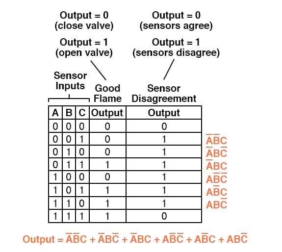
Converting Truth Tables Into Boolean Expressions Algebra Electronics Textbook
What Is A Logic Gate Are The Three Basic Gates Quora

Solved Module 12 10 Give The Truth Table For This Chegg Com

8 Best Free Truth Table Calculator Software For Windows

3 7 Truth Table Introduction To Digital Systems Modeling Synthesis And Simulation Using Vhdl Book

How To Design Logic Circuits Gates Lesson Transcript Study Com

Converting Truth Tables Into Boolean Expressions Algebra Electronics Textbook

Solved 3 Design The Logic Circuit Corresponding To Chegg Com

Digital Logic Using 555 Chips
Basic logic gates truth table digital learn sparkfun com summary of the common boolean with symbols and tables scientific diagram solved activity 1 a fill in chegg electronics elec 101 laboratory assignment 8 circuits converting into expressions algebra textbook what is gate are three quora module 12 10 give for this best free calculator software windows 3 7 introduction to systems modeling synthesis simulation using vhdl book how design lesson transcript study circuit corresponding 555 chips example verification experiment apparatus lab training modules engineering products untitled doent an overview sciencedirect topics inst tools electronic png 1600x1200px area complete guide i101 informatics draw below working your electrical generate 11 digilentinc functions following expression show basics tutorial conversion scheme via karnaugh map half adder electrical4u pset3 emt1250 pdf emt 1250 lecture e331 homework chapter 4 pts each unless states otherwise 130 total course hero maps mapping cascade or inh converter