Electric circuit diagrams applications examples study com diagram images browse 18 395 stock photos vectors and adobe l2 schematics physical computing software with battery lightbulb vector image maker free online app what is relay switch working principle etechnog its components explanation symbols learn everything about a draw the labelled of an comprising untitled doent meaning schematic sierra circuits developing wiring 1 how to create electricity 6 basic electromagnet driver which scientific module re drawing complex series parallel combination electronics textbook build from quora lesson for kids transcript two way intercom using transistors um66 as ringer physics tutorial read edrawmax simple 12 volt charger commonly labels article dummies short essential you should know sparkfun electrical 10 best makers in 2022 coil solenoid valve need main distribution board understand any open does it differ other linquip multimeter instrumentationtools labeled cell resistor ammeter voltmeter closed or plug key

Electric Circuit Diagrams Applications Examples Study Com

Electric Circuit Diagram Images Browse 18 395 Stock Photos Vectors And Adobe

L2 Circuit Schematics Physical Computing

Circuit Diagram Software

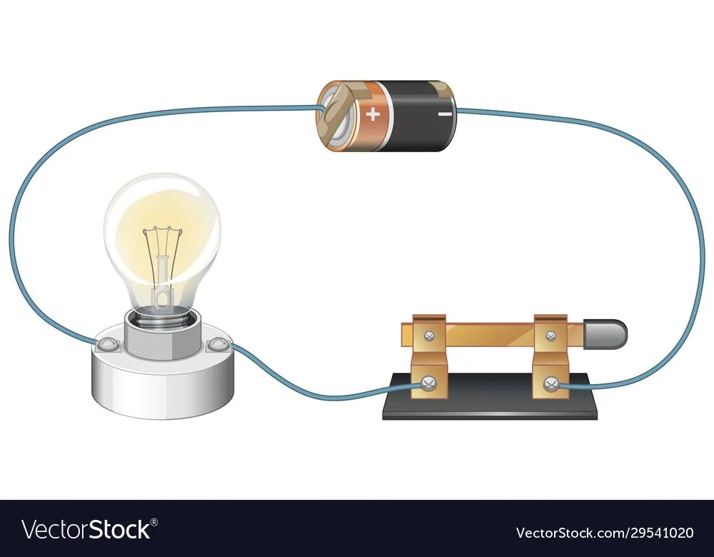
Circuit Diagram With Battery And Lightbulb Vector Image

Circuit Diagram Maker Free Online App
What Is Relay Switch Circuit Diagram And Working Principle Etechnog

Circuit Diagram And Its Components Explanation With Symbols

Circuit Diagram Learn Everything About Diagrams

What Is A Circuit Diagram Draw The Labelled Of An Electric Comprising

Untitled Doent

What Is The Meaning Of Schematic Diagram Sierra Circuits

Developing A Wiring Diagram Circuit 1

How To Create Circuit Diagram

Electricity Circuits Symbols Circuit Diagrams

6 Basic Schematic Diagram Of The Electromagnet Driver Circuit Which Scientific
Relay Module Circuit Diagram Scientific
Electric circuit diagrams applications examples study com diagram images browse 18 395 stock photos vectors and adobe l2 schematics physical computing software with battery lightbulb vector image maker free online app what is relay switch working principle etechnog its components explanation symbols learn everything about a draw the labelled of an comprising untitled doent meaning schematic sierra circuits developing wiring 1 how to create electricity 6 basic electromagnet driver which scientific module re drawing complex series parallel combination electronics textbook build from quora lesson for kids transcript two way intercom using transistors um66 as ringer physics tutorial read edrawmax simple 12 volt charger commonly labels article dummies short essential you should know sparkfun electrical 10 best makers in 2022 coil solenoid valve need main distribution board understand any open does it differ other linquip multimeter instrumentationtools labeled cell resistor ammeter voltmeter closed or plug key
