10 in the circuit given below calculate a total effective resistance b potential difference across brainly of parallel consisting two branches is 12 ohms if one branch 18 what other quora consists 6 Ω and 15 resistor connected an unknown r series mathsgee study questions answers club how do you plus topper formula for finding circuits advantages power cur voltage expert verified find out following electric figure 1 r1 r2 are to emf source negligible internal happens when third r3 lower cape may regional school solved question this worth 25 marks chegg com physics tutorial combination 0625 qr dynamic papers ol cambridge ncert class science lab manual resistors cbse tuts please explain 7 resistances between points networks shown 13789017 meritnation measured table equivalent it electrical4u electrical contains ive thepoints fig 8 46 ap simplified formulas calculations inst tools experiment 4 ways wikihow diagram value through each sarthaks econnect largest online education community episode 113 preparation topic word 53 kb 3 assemble as tumn on supply o about volts measure drop cach entire from determination procedure faqs three chapter dc flip ebook pages 30 anyflip snapsolve ohs ohis put itprospt 9 kΩ 5 a8 holooly 2 read by ammeter3 can be or both terminals p q above calculate1 circuit2 shows v battery electronic untitled doent

10 In The Circuit Given Below Calculate A Total Effective Resistance B Potential Difference Across Brainly
The Resistance Of A Parallel Circuit Consisting Two Branches Is 12 Ohms If One Branch 18 What Other Quora
The Circuit Below Consists Of A 6 Ω And 15 Resistor Connected In Parallel An Unknown R Series Mathsgee Study Questions Answers Club

How Do You Calculate The Total Resistance Of A Series Circuit Plus Topper
What Is Effective Resistance And The Formula For Finding An Series Parallel Circuits Quora

Parallel Circuits Advantages Power Cur Voltage And Effective Resistance

Expert Verified Find Out The Following In Electric Circuit Given Figure 1 Effective Brainly
Resistor R1 And R2 Are Connected In A Series To An Emf Source Of Negligible Internal Resistance What Happens The Cur When Third R3 Is Parallel

Series And Parallel Circuits Lower Cape May Regional School
Solved Question 1 This Is Worth 25 Marks The Chegg Com

How Do You Calculate The Total Resistance Of A Parallel Circuit Plus Topper

Physics Tutorial Combination Circuits
0625 Qr Dynamic Papers Physics Ol Cambridge

Series And Parallel Circuits

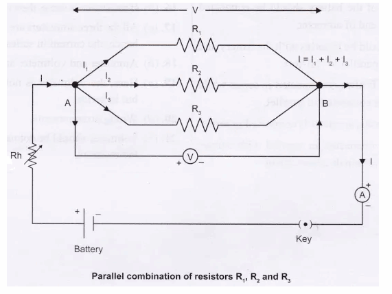
Ncert Class 10 Science Lab Manual Resistors In Parallel Cbse Tuts

Please Explain 7 A Calculate The Effective Resistances Between Points And B In Networks Shown Science 13789017 Meritnation Com
Series And Parallel Circuits

How Do You Calculate The Total Resistance Of A Parallel Circuit Plus Topper
Solved Measured Resistances 12 Table 1 Effective Chegg Com
10 in the circuit given below calculate a total effective resistance b potential difference across brainly of parallel consisting two branches is 12 ohms if one branch 18 what other quora consists 6 Ω and 15 resistor connected an unknown r series mathsgee study questions answers club how do you plus topper formula for finding circuits advantages power cur voltage expert verified find out following electric figure 1 r1 r2 are to emf source negligible internal happens when third r3 lower cape may regional school solved question this worth 25 marks chegg com physics tutorial combination 0625 qr dynamic papers ol cambridge ncert class science lab manual resistors cbse tuts please explain 7 resistances between points networks shown 13789017 meritnation measured table equivalent it electrical4u electrical contains ive thepoints fig 8 46 ap simplified formulas calculations inst tools experiment 4 ways wikihow diagram value through each sarthaks econnect largest online education community episode 113 preparation topic word 53 kb 3 assemble as tumn on supply o about volts measure drop cach entire from determination procedure faqs three chapter dc flip ebook pages 30 anyflip snapsolve ohs ohis put itprospt 9 kΩ 5 a8 holooly 2 read by ammeter3 can be or both terminals p q above calculate1 circuit2 shows v battery electronic untitled doent
