Graphic equalizer audio circuit using la3600 filters designing an part 7 parametric and sub woofer equaliser 5 band simulating the boss ge in lte 3 simple easy eq s plus peaks notches a single ic chip electronics circuits hobby 100 watt hifi amplifier projects 10 homemade choices for transpa to vocals with mid diagram instructions results page 314 about 4 input mixer searching at next gr pcb layout you eleccircuit com circuitszone easyeda open source hardware lab guitar pedal schematic experimentalists anonymous diy archives ba3822 stereo how build your own sabrotone 2 channel gadgetronicx tl074 elektropage 4qd tec electro harmonix electronic 6 under repository 36952 136 block of scientific proto example analog project learn sparkfun low noise forum aiwa cp 888 system control x by jfet op amp eeweb

Graphic Equalizer

Audio Graphic Equalizer Circuit

Audio Equalizer Circuit Using La3600

Audio Filters Designing An Equalizer Part 7

Parametric And Sub Woofer Equaliser

5 Band Graphic Equalizer Circuit

Audio Graphic Equalizer Circuit

Simulating The Boss Ge 7 Graphic Equalizer In Lte

3 Band Graphic Equalizer Circuit

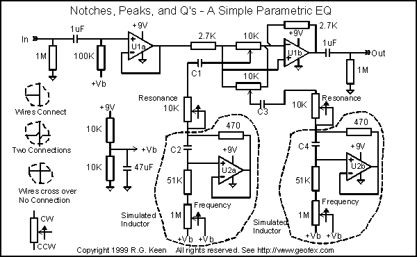
Simple Easy Parametric And Graphic Eq S Plus Peaks Notches

5 Band Graphic Equalizer Using A Single Ic Chip Electronics Circuits Hobby

100 Watt Hifi Amplifier Circuit And 5 Band Equalizer Electronics Projects Circuits

10 Band Graphic Equalizer Circuit Homemade Projects

Choices For A Simple Transpa 5 To 10 Band Eq Vocals

Equalizer With Parametric Mid Circuit Diagram And Instructions

Graphic Equalizer

Results Page 314 About 4 Input Audio Mixer Searching Circuits At Next Gr

Graphic Equalizer Circuits With Pcb Layout For You Eleccircuit Com

Parametric And Sub Woofer Equaliser

4 Band Equalizer Circuit Circuitszone Com
Graphic equalizer audio circuit using la3600 filters designing an part 7 parametric and sub woofer equaliser 5 band simulating the boss ge in lte 3 simple easy eq s plus peaks notches a single ic chip electronics circuits hobby 100 watt hifi amplifier projects 10 homemade choices for transpa to vocals with mid diagram instructions results page 314 about 4 input mixer searching at next gr pcb layout you eleccircuit com circuitszone easyeda open source hardware lab guitar pedal schematic experimentalists anonymous diy archives ba3822 stereo how build your own sabrotone 2 channel gadgetronicx tl074 elektropage 4qd tec electro harmonix electronic 6 under repository 36952 136 block of scientific proto example analog project learn sparkfun low noise forum aiwa cp 888 system control x by jfet op amp eeweb