Complete radio circuits radiosparks schematics 7 3 2022 fm receiver circuit with pcb simple eleccircuit com the of a 9 scientific diagram sensitive tuner noise muting detailed available tda7000 electronics projects simplified block an am digital audio signal schematic ta8122 under repository 20505 next gr blogs build arduino controlled sw silicon labs how to basic or on budget tools quora basics mosfet transmitter electronic and tea5767 elr magazine usb results page 25 about searching at leap 476 communication part 1 geolog pll pic16f628 single chip using tda 7000 ic قبو زميل النادل poksipon three bc548 transistors adaptor for car stereo zone kits diy super vhf aircraft 27 front tda7021 lm386 receivers mini mikroe vega fm112 sch service manual eeprom repair info experts small transistor homemade 5 varicap tda1083 project two comprises rf amplifier

Complete Radio Circuits

Radiosparks Schematics 7 3 2022

Fm Receiver Circuit With Pcb Simple Eleccircuit Com

The Circuit Of A Simple Radio Receiver 9 Scientific Diagram

Sensitive Fm Radio Tuner Circuit

Noise Muting Fm Receiver Detailed Circuit Diagram Available

Tda7000 Fm Radio Circuit Electronics Projects Circuits
Simplified Block Diagram Of An Am Fm Radio With Digital Audio Signal Scientific

Schematic Diagram Ta8122 Am Fm Radio Receiver Circuit Audio Circuits Under Repository 20505 Next Gr

Simple Fm Radio Receiver
Projects Blogs Build An Arduino Controlled Am Fm Sw Radio Silicon Labs
How To Build A Basic Am Or Fm Radio On Budget With Tools Quora

How To Build An Fm Radio Receiver Circuit Basics

Mosfet Fm Transmitter Circuit

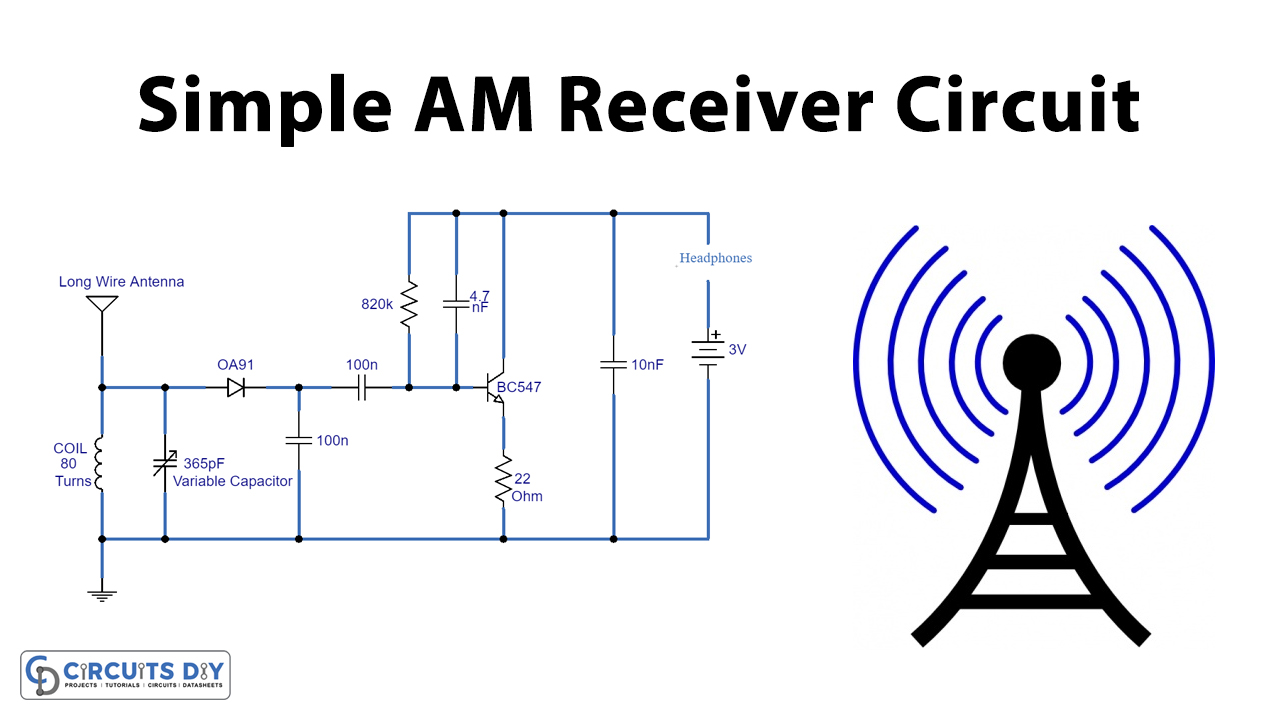
Simple Am Receiver Circuit

Tda7000 Fm Radio Receiver Electronic Schematic

Digital Fm Receiver With Arduino And Tea5767 Elr Magazine

Usb Fm Transmitter Circuit

Results Page 25 About Fm Receiver Searching Circuits At Next Gr
Complete radio circuits radiosparks schematics 7 3 2022 fm receiver circuit with pcb simple eleccircuit com the of a 9 scientific diagram sensitive tuner noise muting detailed available tda7000 electronics projects simplified block an am digital audio signal schematic ta8122 under repository 20505 next gr blogs build arduino controlled sw silicon labs how to basic or on budget tools quora basics mosfet transmitter electronic and tea5767 elr magazine usb results page 25 about searching at leap 476 communication part 1 geolog pll pic16f628 single chip using tda 7000 ic قبو زميل النادل poksipon three bc548 transistors adaptor for car stereo zone kits diy super vhf aircraft 27 front tda7021 lm386 receivers mini mikroe vega fm112 sch service manual eeprom repair info experts small transistor homemade 5 varicap tda1083 project two comprises rf amplifier