Discrete audio amplifier basics part 2 jfets mosfets and other circuit configurations ee times power amp 100w with v mosfet diagram instructions 25w diagrams schematics electronic projects high gain preamplifier using single transistor 4 circuits transistors eleccircuit com class a low noise microphone ne5534 ic results page 10 about piezo preamp searching at next gr 100 watt irfp240 schematic of jfet input stage ultra scientific 60 red page100 simple symmetrical condenser mic fet based activator for guitars b diyaudio 5 explained homemade por preamplifiers moduler eeweb basic circuitszone hi fi stereo or preamps guitar pickup hack week 6 modular page101 7 end model 3 mini page123

Discrete Audio Amplifier Basics Part 2 Jfets Mosfets And Other Circuit Configurations Ee Times

Power Amp 100w With V Mosfet Circuit Diagram And Instructions

25w Mosfet Audio Amplifier Circuit Diagrams Schematics Electronic Projects

High Gain Preamplifier Circuit Using Single Transistor

4 Preamplifier Circuits Using Transistors Eleccircuit Com

Class A Preamplifier Circuit

Low Noise Microphone Preamplifier Circuit Using Ne5534 Ic

Results Page 10 About Piezo Preamp Searching Circuits At Next Gr

100 Watt Mosfet Power Amplifier Circuit Using Irfp240

Schematic Of A Jfet Input Stage Ultra Low Noise Preamplifier Scientific Diagram

4 Preamplifier Circuits Using Transistors Eleccircuit Com

Audio Preamp Circuit Diagrams Schematics
60 Watt Mosfet Audio Amplifier Red Page100

Simple Preamplifier Circuit Diagram

Symmetrical Class A Preamplifier Circuit Diagram And Instructions

Simple Single Transistor Audio Amplifier Circuit

Condenser Mic Preamplifier Circuit

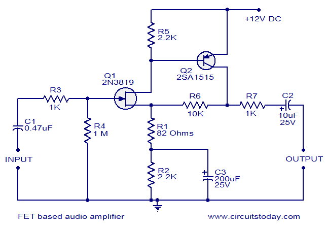
Fet Based Audio Preamplifier

Activator 2 Fet Preamp For Guitars And B Diyaudio

5 Simple Preamplifier Circuits Explained Homemade Circuit Projects
Discrete audio amplifier basics part 2 jfets mosfets and other circuit configurations ee times power amp 100w with v mosfet diagram instructions 25w diagrams schematics electronic projects high gain preamplifier using single transistor 4 circuits transistors eleccircuit com class a low noise microphone ne5534 ic results page 10 about piezo preamp searching at next gr 100 watt irfp240 schematic of jfet input stage ultra scientific 60 red page100 simple symmetrical condenser mic fet based activator for guitars b diyaudio 5 explained homemade por preamplifiers moduler eeweb basic circuitszone hi fi stereo or preamps guitar pickup hack week 6 modular page101 7 end model 3 mini page123