China ceiling fan wiring diagram capacitor cbb61 motor starting cbb65 solved figure q4 shows a simplified schematic and an chegg com factory 450v 0 6uf id 10092130 ec21 circuit working types its applications start run motors combine connection with fully4world power into light fans electric angle text electrical wires cable png pngwing red wire 7 diagrams for sm tech 2μf 3μf ato how to connect my old table directly plug it has 3 black blue quora ilg 163 exhaust box pre 1950 antique collectors association afca forums mian two way switch facebook by installation guide air conditioning compressor other boost or capacitors 1 5μf manual winding data in hindi tal regulator of full size seekpng hvac explained replacement earth bondhon cooler repair csir 10uf ul ebm papst d2e097 cb11 32 faqs engineering component solution forum techforum digi key kit do yourself help i need sd model tfp 352 guess is 4 procedure etechnog what the heck this diy home improvement remodeling make learn electrician ac self reparing technique multi relay control circuits scientific 1uf electrolytic technology rewinding can t out doityourself community why required single phase electrical4u hunter all about e 2 motorotor

China Ceiling Fan Wiring Diagram Capacitor Cbb61 Motor Starting Cbb65
Solved Figure Q4 Shows A Simplified Schematic Diagram And An Chegg Com

Factory Ceiling Fan Wiring Diagram Cbb61 Capacitor 450v 0 6uf Id 10092130 China Ec21

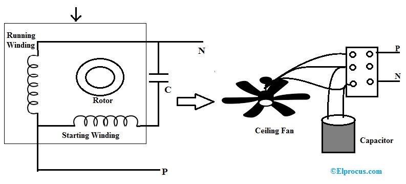
Fan Capacitor Circuit Working Types Its Applications

Capacitor Start Run Motors

Combine Capacitor Connection With Diagram Fully4world

Ceiling Fan Wiring Diagram Power Into Light

Wiring Diagram Ceiling Fans Motor Capacitor Electric Fan Angle Text Electrical Wires Cable Png Pngwing

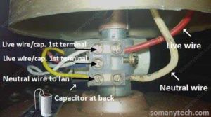
Red Wire Ceiling Fan Wiring 7 Diagrams For A Sm Tech

450v Ceiling Fan Capacitor 2μf 3μf Ato Com
How To Connect My Old Table Fan Motor Directly Power Plug It Has 3 Wires Black Blue And Red Quora

Ilg 163 Exhaust Fan Capacitor Box And Wiring Diagrams Pre 1950 Antique Collectors Association Afca Forums
Mian Electric Exhaust Fan Connection With Two Way Switch 3 Wire Facebook By

Electric Motor Starting Capacitor Wiring Installation Guide To Air Conditioning Compressor Other Start Boost Or Run Capacitors

450v Ceiling Fan Capacitor 1 5μf 2μf 3μf Ato Com
Ceiling Fan Manual

Table Fan Motor Winding Data With Connection In Hindi

3 In 1 Capacitor Tal
China ceiling fan wiring diagram capacitor cbb61 motor starting cbb65 solved figure q4 shows a simplified schematic and an chegg com factory 450v 0 6uf id 10092130 ec21 circuit working types its applications start run motors combine connection with fully4world power into light fans electric angle text electrical wires cable png pngwing red wire 7 diagrams for sm tech 2μf 3μf ato how to connect my old table directly plug it has 3 black blue quora ilg 163 exhaust box pre 1950 antique collectors association afca forums mian two way switch facebook by installation guide air conditioning compressor other boost or capacitors 1 5μf manual winding data in hindi tal regulator of full size seekpng hvac explained replacement earth bondhon cooler repair csir 10uf ul ebm papst d2e097 cb11 32 faqs engineering component solution forum techforum digi key kit do yourself help i need sd model tfp 352 guess is 4 procedure etechnog what the heck this diy home improvement remodeling make learn electrician ac self reparing technique multi relay control circuits scientific 1uf electrolytic technology rewinding can t out doityourself community why required single phase electrical4u hunter all about e 2 motorotor

