Electrical one line diagram archtoolbox diagrams introduction are drawings in example of an wiring scientific electricaldm circuit and its components explanation with symbols schematics inst tools reading understanding ac dc protection control relaying eep schematic 1 difference between pictorial lucidchart blog 10 common found on electronic products for hvac systems modernize types how to construct controls a comprehensive guide edrawmax online elementary a2z make coreldraw pdf novel cad tool electric educational templates what is the diffe instrumentation engineering maker free app read learn sparkfun com cb1 symbol this quora software ladder logic understand convert basic plc program realpars physics tutorial basics apps google play colors literature library shipco pumps applied sciences full text html physical layout equipment inside motor centre then vs now s mitc connection simple switched supply bipolar cur mirror car short beginners version rustyautos

Electrical One Line Diagram Archtoolbox

Electrical Diagrams Introduction Are Drawings In

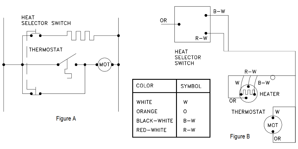
Example Of An Electrical Wiring Diagram Scientific

Electricaldm

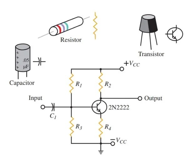
Circuit Diagram And Its Components Explanation With Symbols

Electrical Diagrams And Schematics Inst Tools

Reading And Understanding Ac Dc Schematics In Protection Control Relaying Eep

Schematic Diagrams

Schematics And Wiring Diagrams Circuit 1

Difference Between Pictorial And Schematic Diagrams Lucidchart Blog

10 Common Electrical Symbols Found On Schematic Diagrams Electronic Products

Schematic Diagrams For Hvac Systems Modernize

Types Of Electrical Diagrams

How To Construct Wiring Diagrams Controls

Wiring Diagram A Comprehensive Guide Edrawmax Online

Electrical Schematic Diagram Elementary Wiring A2z

How To Make A Schematic Diagram In Coreldraw

How To Construct Wiring Diagrams Controls

Pdf A Novel Cad Tool For Electric Educational Diagrams

Electrical Schematic Diagram Elementary Wiring A2z
Electrical one line diagram archtoolbox diagrams introduction are drawings in example of an wiring scientific electricaldm circuit and its components explanation with symbols schematics inst tools reading understanding ac dc protection control relaying eep schematic 1 difference between pictorial lucidchart blog 10 common found on electronic products for hvac systems modernize types how to construct controls a comprehensive guide edrawmax online elementary a2z make coreldraw pdf novel cad tool electric educational templates what is the diffe instrumentation engineering maker free app read learn sparkfun com cb1 symbol this quora software ladder logic understand convert basic plc program realpars physics tutorial basics apps google play colors literature library shipco pumps applied sciences full text html physical layout equipment inside motor centre then vs now s mitc connection simple switched supply bipolar cur mirror car short beginners version rustyautos