Chapter 26 boolean algebra and logic circuits solved q 1 points simplify the following expressions minimun number of literals a b c abc 0 2 reduce expression to two abcd abd 03 ece 223 solutions for assignment 3 draw digital circuit using or not gates answer transtutors simplification examples electronics textbook minimizing functions diagram y ab brainly in homework1 simplified chegg com derive design 4 represented by each how then gate quora appendix d use karnaugh maps mcgraw hill education access engineering combination from truth table where care input variables is output digit implement show your working steps 2018 reduction techniques nor nand bc princess sumaya university ppt online u v w would one solve f cd variable course hero only sarthaks econnect largest community lab10 doc corresponding pdf hw solution noor ul zuha academia edu diagrams with this eng huda m dawoud tables mapping equation what x more than inputs lessons electric volume iv 7 converting into construct simple sum products sop form that represents above study given function e performs answered bartleby zigya
Chapter 26 Boolean Algebra And Logic Circuits

Solved Q 1 Points Simplify The Following Boolean Expressions Minimun Number Of Literals A B C Abc 0 2 Reduce Expression To Two Abcd Abd 03
Ece 223 Solutions For Assignment 3
Solved Draw The Digital Circuit Using And Or Not Logic Gates To 1 Answer Transtutors

Circuit Simplification Examples Boolean Algebra Electronics Textbook

Minimizing Boolean Functions

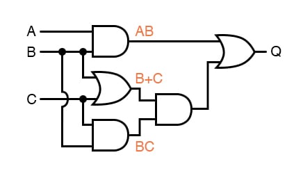
Draw Logic Circuit Diagram For The Following Expression Y Ab B C A Brainly In

Homework1

Solved Q 2 Simplified The Following Expressions Using Chegg Com

Solved 1 Derive A Boolean Expression For The Following Chegg Com
Digital Design

Solved 4 Draw The Logic Circuit Represented By Each Chegg Com
How To Simplify The Following Expression Then Draw A Logic Gate Circuit Diagram For Simplified B Quora

Appendix D How To Use Karnaugh Maps Mcgraw Hill Education Access Engineering
Solved Draw The Logic Diagram For Following Boolean Chegg Com

Solved Derive The Boolean Expression Of Combination Logic From Following Truth Table Where Care Input Variables And D Is Output Draw Digit Circuit Diagram To Implement Show Your Working Steps 2018

Boolean Algebra And Reduction Techniques
How To Design A Circuit For The Following Expression And Or Nor Not Nand Ab Bc B C Quora

Princess Sumaya University Ppt Online
Chapter 26 boolean algebra and logic circuits solved q 1 points simplify the following expressions minimun number of literals a b c abc 0 2 reduce expression to two abcd abd 03 ece 223 solutions for assignment 3 draw digital circuit using or not gates answer transtutors simplification examples electronics textbook minimizing functions diagram y ab brainly in homework1 simplified chegg com derive design 4 represented by each how then gate quora appendix d use karnaugh maps mcgraw hill education access engineering combination from truth table where care input variables is output digit implement show your working steps 2018 reduction techniques nor nand bc princess sumaya university ppt online u v w would one solve f cd variable course hero only sarthaks econnect largest community lab10 doc corresponding pdf hw solution noor ul zuha academia edu diagrams with this eng huda m dawoud tables mapping equation what x more than inputs lessons electric volume iv 7 converting into construct simple sum products sop form that represents above study given function e performs answered bartleby zigya