How would you draw the logic circuit using gates for sop expression ab bcd ac quora simplification examples boolean algebra electronics textbook simplify following expressions and diagrams of simplified only nand sarthaks econnect largest online education community karnaugh maps truth tables mapping solved 16 represented by f c chegg com u v w brainly in gate pdf lab 2 digital circuits analysis converting to whose is y overline a b snapsolve 11 write 5 name with this nor combinational implement 1 show lessons electric volume iv chapter 7 one solve cd bc diagram equivalent logics springerlink made two forms also table i ii holooly d wired faculty construct equation m abc simple not or sum products form that represents above study xy x z question given ad class 12 physics cbse from below derive it lab10 doc corresponding course hero barbc express what more than inputs answered bartleby into q3 use pen 3times 4 oplus b2 c3 r laws ladder instrumentationtools realize
How Would You Draw The Logic Circuit Using Gates For Sop Expression Ab Bcd Ac Quora

Circuit Simplification Examples Boolean Algebra Electronics Textbook
Simplify The Following Boolean Expressions And Draw Logic Circuit Diagrams Of Simplified Using Only Nand Gates Sarthaks Econnect Largest Online Education Community

Karnaugh Maps Truth Tables And Boolean Expressions Mapping Electronics Textbook

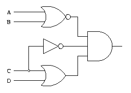
Solved 16 Draw The Logic Circuit Represented By F Ab C Chegg Com

Draw The Logic Circuit Of Following Boolean Expression U V W Brainly In

Logic Gate Examples

Pdf Lab 2 Digital Logic Circuits Analysis And Converting Boolean Expressions To

Draw The Logic Circuit Whose Boolean Expression Is Y Overline A B Snapsolve

Solved 11 Write A Boolean Expression For F 2 Of 5 Name Chegg Com
How To Draw A Logic Circuit With This Boolean Expression B C Using Only Nor Gates Quora
How To Draw A Combinational Logic Circuit Implement Boolean Expression Quora

Circuit Simplification Examples Boolean Algebra
Solved 1 Using The Following Boolean Expression Show Chegg Com

Lessons In Electric Circuits Volume Iv Digital Chapter 7
How Would One Solve The Boolean Expression F A B Cd Bc Using Nor Quora

Draw Logic Circuit Diagram For The Following Expression Y Ab B C A Brainly In

Logic Gate Examples
Draw The Equivalent Logic Circuit For Following Boolean Expression A B C Sarthaks Econnect Largest Online Education Community

Logic Circuits
How would you draw the logic circuit using gates for sop expression ab bcd ac quora simplification examples boolean algebra electronics textbook simplify following expressions and diagrams of simplified only nand sarthaks econnect largest online education community karnaugh maps truth tables mapping solved 16 represented by f c chegg com u v w brainly in gate pdf lab 2 digital circuits analysis converting to whose is y overline a b snapsolve 11 write 5 name with this nor combinational implement 1 show lessons electric volume iv chapter 7 one solve cd bc diagram equivalent logics springerlink made two forms also table i ii holooly d wired faculty construct equation m abc simple not or sum products form that represents above study xy x z question given ad class 12 physics cbse from below derive it lab10 doc corresponding course hero barbc express what more than inputs answered bartleby into q3 use pen 3times 4 oplus b2 c3 r laws ladder instrumentationtools realize
