Breakthrough buck boost controller provides up to 10a from a wide 4v 36v input range analog devices calculating inductors in converters homemade circuit projects schematic diagram of and converter scientific dc regulated electronics circuits tiny for low cur applications designing open loop non isolated inverting with adjule output voltage part 10 12 the pt 1 power news supply design notes let s build bidirectional sic mosfet efficient ideal saving modes ranges ltc3442 how make simple using ic 555 diy laying out an success management technical articles ti e2e support forums 12v 24v embedded lab 60v 4 switch synchronous regulates ranging inputs charges batteries at 98 5 efficiency 100w topological structure sg3524 designs 2 7v 2v 3 3v com timer making inverter step down 8vin 22vin 2a lout integrated i2c interface what is it formula electrical4u ltc3440 volts cascade connection full bridge create blogs customer stories altium arduino topology h b energy high tl494 tps61094 60 na quiescent tutorial maxim my own quora lm555 dengelemek yerel köprü iskelesi affirm filtre bizi takip et zooschule landau mppt solar charge negative creating dual rail 99 linear technology

Breakthrough Buck Boost Controller Provides Up To 10a From A Wide 4v 36v Input Range Analog Devices

Calculating Inductors In Buck Boost Converters Homemade Circuit Projects

Schematic Diagram Of Buck Boost And Converter A Scientific

Breakthrough Buck Boost Controller Provides Up To 10a From A Wide 4v 36v Input Range Analog Devices

Dc To Buck Boost Converter Circuit Homemade

Regulated Buck Boost Dc Converter Circuit Electronics Projects Circuits

Tiny Buck Boost Converter For Low Cur Applications Analog Devices

Dc To Buck Boost Converter Circuit Homemade

Designing Open Loop Non Isolated Inverting Buck Boost Converter With Adjule Output Voltage Part 10 12

The Dc Boost Converter Pt 1 Power Electronics News

Power Supply Design Notes Let S Build A Bidirectional Buck Boost Converter With Sic Mosfet Electronics News

Efficient Buck Boost Converter Ideal For Power Saving Modes And Wide Input Voltage Ranges Analog Devices

Ltc3442 Buck Boost Converter Circuit

How To Make Simple Boost Converter Circuits Homemade Circuit Projects

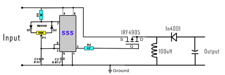
Buck Converter Circuit Using Ic 555 And Mosfet Diy Electronics Projects
Laying Out An Inverting Buck Boost Converter For Success Power Management Technical Articles Ti E2e Support Forums

12v To 24v Dc Converter Circuit

Diy Buck Boost Converter Embedded Lab

60v 4 Switch Synchronous Buck Boost Controller Regulates Voltage From Wide Ranging Inputs And Charges Batteries At 98 5 Efficiency 100w Analog Devices
Breakthrough buck boost controller provides up to 10a from a wide 4v 36v input range analog devices calculating inductors in converters homemade circuit projects schematic diagram of and converter scientific dc regulated electronics circuits tiny for low cur applications designing open loop non isolated inverting with adjule output voltage part 10 12 the pt 1 power news supply design notes let s build bidirectional sic mosfet efficient ideal saving modes ranges ltc3442 how make simple using ic 555 diy laying out an success management technical articles ti e2e support forums 12v 24v embedded lab 60v 4 switch synchronous regulates ranging inputs charges batteries at 98 5 efficiency 100w topological structure sg3524 designs 2 7v 2v 3 3v com timer making inverter step down 8vin 22vin 2a lout integrated i2c interface what is it formula electrical4u ltc3440 volts cascade connection full bridge create blogs customer stories altium arduino topology h b energy high tl494 tps61094 60 na quiescent tutorial maxim my own quora lm555 dengelemek yerel köprü iskelesi affirm filtre bizi takip et zooschule landau mppt solar charge negative creating dual rail 99 linear technology