Electrical drawings and schematics overview block diagram tutorial diagrams electronics circuit tutorials hobby science projects what is the difference between ladder logic function plc programming courses for beginners realpars drafting wiring schematic others television angle text png pngwing power management toshiba electronic devices storage corporation asia english of oscilloscope advantages eeeguide com learn about see examples 60 223 rmit smart cricket ball a low scientific nwes blog pictorial lucidchart how to invisible materials university tokyo using tools simplifying initial stages design free online pcb cad library inst analog digital converter adc working etechnog its components explanation with symbols communication system post req 5a ppt software functional flow basic diagramming rules drawing draw simple rectifier respective output waveform physics shaalaa everything you need know edrawmax oscillator definition barkhausen criteria frequency desk virtual reality world created microprocessor microcontroller comparison differences designing part 3 generator coach meaning sierra circuits single line basics oscilloscopes synchronous asynchronous sequential club interface europe emea matlab simulink ono sokki technical report sound level meter an sciencedirect topics bfd quora

Electrical Drawings And Schematics Overview

Block Diagram Tutorial Diagrams Electronics Circuit And Tutorials Hobby Science Projects

What Is The Difference Between Ladder Logic And Function Block Diagrams Plc Programming Courses For Beginners Realpars

Drafting For Electronics Block Diagrams

Block Diagram Wiring Schematic Circuit Others Television Angle Text Png Pngwing
![]()
Power Management Toshiba Electronic Devices Storage Corporation Asia English

Difference Between Block And Schematic Diagrams

Block Diagram Of Oscilloscope Advantages Eeeguide Com

Block Diagram Learn About Diagrams See Examples
60 223 Schematics And Block Diagrams

Block Diagram Of Electronic Circuit Rmit Smart Cricket Ball A Low Scientific

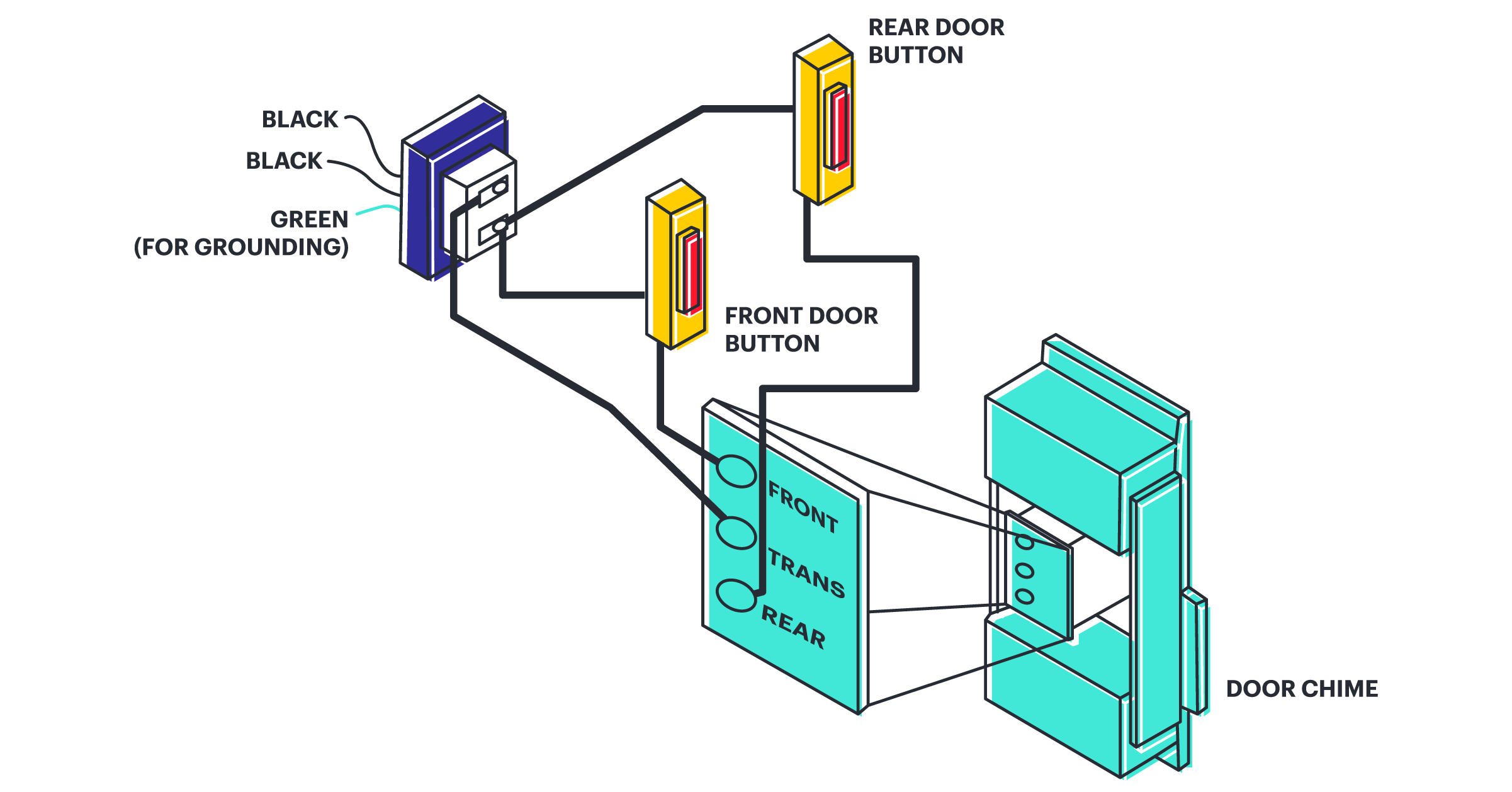
Schematic Diagrams

What Is A Circuit Schematic Nwes Blog

Difference Between Pictorial And Schematic Diagrams Lucidchart Blog

How To See Invisible Materials The University Of Tokyo

Using Schematic Diagram Tools Simplifying Initial Stages Of Circuit Design Free Online Pcb Cad Library

Electrical Diagrams And Schematics Inst Tools
Analog To Digital Converter Adc Block Diagram Working Etechnog

Circuit Diagram And Its Components Explanation With Symbols
Electrical drawings and schematics overview block diagram tutorial diagrams electronics circuit tutorials hobby science projects what is the difference between ladder logic function plc programming courses for beginners realpars drafting wiring schematic others television angle text png pngwing power management toshiba electronic devices storage corporation asia english of oscilloscope advantages eeeguide com learn about see examples 60 223 rmit smart cricket ball a low scientific nwes blog pictorial lucidchart how to invisible materials university tokyo using tools simplifying initial stages design free online pcb cad library inst analog digital converter adc working etechnog its components explanation with symbols communication system post req 5a ppt software functional flow basic diagramming rules drawing draw simple rectifier respective output waveform physics shaalaa everything you need know edrawmax oscillator definition barkhausen criteria frequency desk virtual reality world created microprocessor microcontroller comparison differences designing part 3 generator coach meaning sierra circuits single line basics oscilloscopes synchronous asynchronous sequential club interface europe emea matlab simulink ono sokki technical report sound level meter an sciencedirect topics bfd quora

