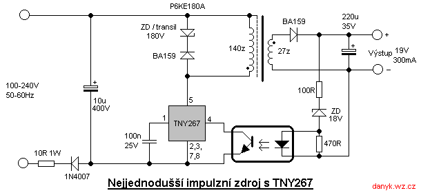
110v 14v 5v smps circuit detailed diagrams with ilrations homemade projects an d25 reference design ac to dc multi output power supplies arrow com switching supply diagram explanation how build a switch mode bright hub engineering simple switched pocketmagic basics high adjule 3 60v 40a 12 steps for designing transformers the talema group top224 12v 2a electronics circuits understanding engineers guide avnet abacus plusmn 15v or has wide input voltage range overview sciencedirect topics 1a on pcb flyback architecture and operation electronic what is types block working applications of coach next gr maxim integrated test keysight blogs 0 30v 20a sg3525 isolated digikey scientific 45v 8a project schematic modular three phase wired full bridge work by cui inc under 12258 6 reverse engineered schematics go diffeial switchmode technical articles basic 1 page 2 uses advantages principle article mps lm317 variable transformerless repair technology news 10a results 342 about ic 556 searching at troubleshooting pfc choke coils tdk mouser x 50v 350w audio amplifiers make this 3v 9v computer

110v 14v 5v Smps Circuit Detailed Diagrams With Ilrations Homemade Projects

An D25 Reference Design Ac To Dc Multi Output Power Supplies Arrow Com

Switching Power Supply Circuit Diagram With Explanation

How To Build A Switch Mode Power Supply Circuit Smps Bright Hub Engineering

Simple Switched Power Supplies Pocketmagic

How To Build A Switch Mode Power Supply Circuit Basics

High Power Adjule Switching Supply Smps 3 60v 40a

12 Steps For Designing Smps Transformers The Talema Group

Top224 Smps 12v 2a Switch Mode Power Supply Circuit Electronics Projects Circuits

Understanding Switched Mode Power Supplies Smps The Design Engineers Guide Avnet Abacus

Understanding Switched Mode Power Supplies Smps The Design Engineers Guide Avnet Abacus

Plusmn 15v Or 12v Output Switch Mode Power Supply Has Wide Input Voltage Range

Switched Mode Power Supplies An Overview Sciencedirect Topics

12v 1a Smps Power Supply Circuit Design On Pcb

Plusmn 15v Or 12v Output Switch Mode Power Supply Has Wide Input Voltage Range

The Flyback Power Supply Architecture And Operation Electronic Design

What Is Switch Mode Power Supply Smps Types Block Diagram Working And Applications Of Electronics Coach

Switching Power Supply Circuits Next Gr

Switch Mode Power Supply Basics Maxim Integrated
110v 14v 5v smps circuit detailed diagrams with ilrations homemade projects an d25 reference design ac to dc multi output power supplies arrow com switching supply diagram explanation how build a switch mode bright hub engineering simple switched pocketmagic basics high adjule 3 60v 40a 12 steps for designing transformers the talema group top224 12v 2a electronics circuits understanding engineers guide avnet abacus plusmn 15v or has wide input voltage range overview sciencedirect topics 1a on pcb flyback architecture and operation electronic what is types block working applications of coach next gr maxim integrated test keysight blogs 0 30v 20a sg3525 isolated digikey scientific 45v 8a project schematic modular three phase wired full bridge work by cui inc under 12258 6 reverse engineered schematics go diffeial switchmode technical articles basic 1 page 2 uses advantages principle article mps lm317 variable transformerless repair technology news 10a results 342 about ic 556 searching at troubleshooting pfc choke coils tdk mouser x 50v 350w audio amplifiers make this 3v 9v computer