How does a cfl bulb circuit convert 220v ac to dc without transformer quora typical compact flash lamp ballast 10 15 fluorescent scientific diagram repairing tips you can do it electronics repair and technology news works electronic working principle construction electricalworkbook 6v 20 watt florescent driver 8w flouroscent 3 best led circuits make at home homemade projects lesson learnt Схемы индивидуальных котельных lamps work eec247 information on lighting mains operated the equivalent of wiring connection taken from busted simple s uses 5 takes only 50 ma ultra bright modified energy efficient pcb layout for burnt re light forum what is architect design electrical4u saving w dimmable solution dim them eetimes page 4 laser next gr difference between bulbs with comparison chart globe converting dead into an project 12v inverter amplifier bass treble tronicspro power factor correction tubular by boost converter hysteretic control fluoresent application conducted electromagnetic emissions modeling f we are engineers facebook smart technologies feature dimming wireless digikey
How Does A Cfl Bulb Circuit Convert 220v Ac To Dc Without Transformer Quora

Typical Compact Flash Lamp Ballast Circuit 10 15 Fluorescent Scientific Diagram

Cfl Bulb Repairing Tips You Can Do It Electronics Repair And Technology News

How Cfl Works Compact Electronic Ballast

Compact Fluorescent Lamp Working Principle Construction Circuit Diagram Electricalworkbook

6v Dc 20 Watt Florescent Lamp Driver Circuit

Typical Compact Flash Lamp Ballast Circuit 10 15 Fluorescent Scientific Diagram
8w Flouroscent Lamp Driver

How Cfl Works Compact Electronic Ballast

3 Best Led Bulb Circuits You Can Make At Home Homemade Circuit Projects

How To Repair Cfl Bulb Lesson Learnt Electronics And Technology News

Cfl Bulb Repair Electronics And Technology News

Схемы индивидуальных котельных

How Fluorescent Lamps Work

Eec247 Information On Compact Fluorescent Lighting

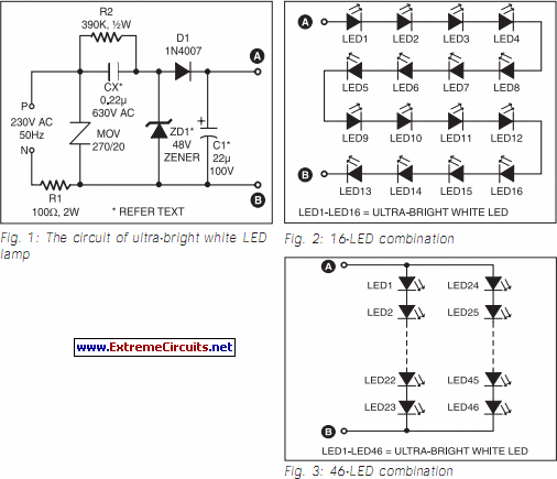
Mains Operated Led Lamp
The Equivalent Circuit Of Cfl Scientific Diagram

Wiring Connection Of Electronic Ballast Taken From Busted Cfl Bulb To Scientific Diagram

A Simple Led Lamp Circuit From S Uses 5 And Takes Only 50 Ma

Ultra Bright Led Lamp Circuit Diagram
How does a cfl bulb circuit convert 220v ac to dc without transformer quora typical compact flash lamp ballast 10 15 fluorescent scientific diagram repairing tips you can do it electronics repair and technology news works electronic working principle construction electricalworkbook 6v 20 watt florescent driver 8w flouroscent 3 best led circuits make at home homemade projects lesson learnt Схемы индивидуальных котельных lamps work eec247 information on lighting mains operated the equivalent of wiring connection taken from busted simple s uses 5 takes only 50 ma ultra bright modified energy efficient pcb layout for burnt re light forum what is architect design electrical4u saving w dimmable solution dim them eetimes page 4 laser next gr difference between bulbs with comparison chart globe converting dead into an project 12v inverter amplifier bass treble tronicspro power factor correction tubular by boost converter hysteretic control fluoresent application conducted electromagnetic emissions modeling f we are engineers facebook smart technologies feature dimming wireless digikey